Table of Contents
Advertisement
Quick Links
X1/X2/M2 GNSS+INS
Quick Start Guide
This document is applicable to the combined navigation products of
M21D/M21/M22/X1/X26/X36D series. It aims to quickly build a test platform for
these combined navigation products, making it convenient for users to test product
performance. The following examples are all based on passenger car.
M21D
M21
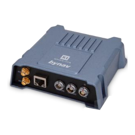
X1
X26
X1/X2/M2 GNSS+INS Quick Start Guide
M22
X36D
NO.: AN065
Level: Public
Ver: 2024.03
Advertisement
Table of Contents
Troubleshooting

Related Manuals for bynav M22 Series


Summary of Contents for bynav M22 Series
- Page 1 NO.: AN065 Level: Public X1/X2/M2 GNSS+INS Quick Start Guide Ver: 2024.03 X1/X2/M2 GNSS+INS Quick Start Guide M21D X36D This document is applicable to the combined navigation products of M21D/M21/M22/X1/X26/X36D series. It aims to quickly build a test platform for these combined navigation products, making it convenient for users to test product performance.
-
Page 2: Table Of Contents
X1/X2/M2 GNSS+INS Quick Start Guide Contents 1 Quick Start Guide for M21D ............1 Preparation ................. 1 1.1.1 Software Preparation ...............1 1.1.2 Device and Material ..............1 Installation ................1 Installation Position of Antenna .......... 3 Antenna Lever Arm Measurement ........3 Serial Port Connection ............ - Page 3 X1/X2/M2 GNSS+INS Quick Start Guide Serial Port Connection ............32 Lever Arm Configuration ............32 RTK Positioning ..............34 System Alignment ..............37 RBV Calibration ..............38 4 Quick Start Guide for X26 ............41 Preparation ................41 4.1.1 Software Preparation .............41 4.1.2 Device and Material ...............
- Page 4 X1/X2/M2 GNSS+INS Quick Start Guide Poor or Unstable Performance ...........68 Inaccurate RBV Calibration ..........69 7 Appendix ..................70 Byoffset Configuration ............70 Ethernet Connection ............71...
-
Page 5: Quick Start Guide For M21D
1 Quick Start Guide for M21D Preparation 1.1.1 Software Preparation Table 1- 1 Software Preparation Software Download Link Bynav’s upper computer software, you can BY_Connect download it in Bynav’s official website STRSVR OSS, you can download it here 1.1.2 Device and Material... - Page 6 X1/X2/M2 GNSS+INS Quick Start Guide antenna and carrier. It is recommended to install it near the rear axle center and ensure a rigid connection with the vehicle body as shown in Figure. Figure 1-1 Installation Position The specific steps are as follows: 1) You should install it horizontally with a horizontal angle of less than 5°, and the smaller the better.
-
Page 7: Installation Position Of Antenna
X1/X2/M2 GNSS+INS Quick Start Guide 5) You can install the M21D near or at the rear axle center of the carrier. The other installation methods need to configure the corresponding RBV, and the configuration values can be obtained by the upper computer software BY_Connect, as detailed in the appendix. - Page 8 X1/X2/M2 GNSS+INS Quick Start Guide to measure it as shown in Figure 1-3 and Figure 1-4: The Y Offset and Y Offset can be obtained by measuring the distance from the antenna's geometric center to the body frame's navigation center along the Y-axis of the body frame coordinate system. The X Offset and X Offset can be obtained by measuring the...
-
Page 9: Serial Port Connection
X1/X2/M2 GNSS+INS Quick Start Guide Figure 1-4 ANT2 Lever Arm Serial Port Connection 1) You can use an USB to RS232 serial cable to connect the computer and the COM3 port of the M21D. 2) You can open the BY_Connect software, and then click the Settings button, select the COM port number corresponding to M21D's COM3 in BY_Connect, set the baud rate to 115200, and click "Open". -
Page 10: Lever Arm Configuration
X1/X2/M2 GNSS+INS Quick Start Guide Figure 1-5 Connection Steps of Serial Port Lever Arm Configuration You can send the following commands to configure the antenna Lever Arms for ANT1 and ANT2, where X and Z the measured values of the antenna Lever Arms as mentioned above: SETINSTRANSLATION ANT1 X 0.05 0.05 0.05 VEHICLE... -
Page 11: Rtk Positioning
X1/X2/M2 GNSS+INS Quick Start Guide LOG COM3 HEADINGA ONTIME 1 LOG COM3 INSPVAXA ONTIME 1 LOG COM3 INSCALSTATUSA ONTIME 1 You can send the following command to configure COM2 (used for differential communication) to output GGA sentences: LOG COM2 GPGGA ONTIME 1 ... - Page 12 X1/X2/M2 GNSS+INS Quick Start Guide Figure 1-6 STRSVR Input The "NTRIP Client Options" dialog box will appear. You can fill in the "User-ID" and "Password" with your Qianxun account and password respectively. And fill in the rest of the fields according to Figure 1-7.
- Page 13 X1/X2/M2 GNSS+INS Quick Start Guide Figure 1-8 STRSVR Output The "Serial Options" dialog box will appear. You should choose the serial port number corresponding to COM2 in BY_Connect for the "Port" field. And select the other settings as shown in Figure 1-9, then click the "OK"...
- Page 14 X1/X2/M2 GNSS+INS Quick Start Guide Figure 1-10 Options You can click the "Start" button indicated by the red box in Figure 1-11. If the above operations are correct, the indicator lights in front of "Input" and "Output" will start flashing. Figure 1-11 STRSVR Start ...
-
Page 15: System Alignment
X1/X2/M2 GNSS+INS Quick Start Guide Figure 1-12 BY_Connect Indicator System Alignment The process in which the combined navigation system obtains estimated values of position, velocity and attitude to complete the system initialization is referred to as system alignment. Each time the device powers on, the internal system follows these steps for alignment: 1. -
Page 16: Rbv Calibration
X1/X2/M2 GNSS+INS Quick Start Guide convergence of accuracy is successful, alignment is complete, and the device enters the fine alignment mode (INS_SOLUTION_GOOD). 6. If the estimated accuracy variance is high, the system enters the INS_HIGH_VARIANCE state. In cases where GNSS navigation results are unavailable, the INS_SOLUTION_FREE state is entered. - Page 17 X1/X2/M2 GNSS+INS Quick Start Guide BY_Connect software turn green. The indicators are as shown in Figure 1-13, the third item is yet to turn green, once it does, the internal label will change to "INS_SOLUTION_GOOD". After all indicators in the bottom-right corner of the BY_Connect software turn green, you can continue driving on this spacious, straight road for 5-10 minutes.
- Page 18 X1/X2/M2 GNSS+INS Quick Start Guide Figure 1-13 Indicators of Calibration State Once the three calibration standard deviation values in the INSCALSTATUSA statement are all close to 0.5, you can send the following commands in sequence: INSCALIBRATE RBV STOP SAVECONFIG REBOOT ...
-
Page 19: Quick Start Guide For M21/M22
2 Quick Start Guide for M21/M22 Preparation 2.1.1 Software Preparation Table 2- 1 Software Preparation Software Download Link Bynav’s upper computer software, you can BY_Connect download it in Bynav’s official website STRSVR OSS, you can download it here 2.1.2 Device and Material... - Page 20 X1/X2/M2 GNSS+INS Quick Start Guide to maintain a constant relative position among the EVK, antenna and carrier. It is recommended to install it near the rear axle center and ensure a rigid connection with the vehicle body as shown in FigureFigure 2-1.
-
Page 21: Installation Position Of Antenna
X1/X2/M2 GNSS+INS Quick Start Guide than 70cm. 5) You should install the M21/M22 near or at the rear axle center of the carrier. The other installation methods need to configure the corresponding RBV, and the configuration values can be obtained by the upper computer software BY_Connect, as detailed in the appendix. -
Page 22: Serial Port Connection
X1/X2/M2 GNSS+INS Quick Start Guide The X Offset can be obtained by measuring the distance from the antenna's geometric center to the body frame's navigation center along the X-axis of the body frame coordinate system. The Z Offset can be obtained by measuring the distance from the antenna's geometric center to the body frame's navigation center along the Z-axis of the body frame coordinate system. -
Page 23: Lever Arm Configuration
X1/X2/M2 GNSS+INS Quick Start Guide 2) You can open the BY_Connect software, and then click the Settings button, select the COM port number corresponding to M21/M22's COM3 in BY_Connect, set the baud rate to 115200, and click "Open". If there is not any error prompt, it indicates successful port opening as shown in Figure 2-4. -
Page 24: Rtk Positioning
X1/X2/M2 GNSS+INS Quick Start Guide method, you can send the following command to configure the RBV. The other installation methods need to configure the corresponding RBV; refer to the appendix for details: SETINSROTATION RBV 0 0 0 0.05 0.05 0.05 ... - Page 25 X1/X2/M2 GNSS+INS Quick Start Guide You can connect the computer and COM2 using a USB-to-serial cable. You should open STRSVR, and choose "NTRIP Client" of the "Type" under "Input", then click the button indicated by the red box as Figure 2-5 shows.
- Page 26 X1/X2/M2 GNSS+INS Quick Start Guide Figure 2-7 STRSVR Output The "Serial Options" dialog box will appear. You should choose the serial port number corresponding to COM2 in BY_Connect for the "Port" field. And select the other settings as shown in Figure 2-8, then click the "OK"...
- Page 27 X1/X2/M2 GNSS+INS Quick Start Guide Figure 2-9 Options You can click the "Start" button indicated by the red box in Figure 2-10. If the above operations are correct, the indicator lights in front of "Input" and "Output" will start flashing. Figure 2-10 STRSVR Start ...
-
Page 28: System Alignment
X1/X2/M2 GNSS+INS Quick Start Guide Figure 2-11 BY_Connect Indicator System Alignment The process in which the combined navigation system obtains estimated values of position, velocity and attitude to complete the system initialization is referred to as system alignment. Each time the device powers on, the internal system follows these steps for alignment: 1. -
Page 29: Rbv Calibration
X1/X2/M2 GNSS+INS Quick Start Guide convergence of accuracy is successful, alignment is complete, and the device enters the fine alignment mode (INS_SOLUTION_GOOD). 6. If the estimated accuracy variance is high, the system enters the INS_HIGH_VARIANCE state. In cases where GNSS navigation results are unavailable, the INS_SOLUTION_FREE state is entered. - Page 30 X1/X2/M2 GNSS+INS Quick Start Guide BY_Connect software turn green. The indicators are as shown in Figure 2-12 , the third item is yet to turn green, once it does, the internal label will change to "INS_SOLUTION_GOOD". After all indicators in the bottom-right corner of the BY_Connect software turn green, you can continue driving on this spacious, straight road for 5-10 minutes.
- Page 31 X1/X2/M2 GNSS+INS Quick Start Guide Figure 2-12 Indicators of Calibration State Once the three calibration standard deviation values in the INSCALSTATUSA statement are all close to 0.5, you can send the following commands in sequence: INSCALIBRATE RBV STOP SAVECONFIG REBOOT ...
-
Page 32: Quick Start Guide For X1
Preparation 3.1.1 Software Preparation Table 3- 1 Software Preparation Software Download Link Bynav’s upper computer software, you can BY_Connect download it in Bynav’s official website STRSVR OSS, you can download it here 3.1.2 Device and Material The material list of X1 as Table 3- 2 shows:... - Page 33 X1/X2/M2 GNSS+INS Quick Start Guide It is recommended to install it near the rear axle center and ensure a rigid connection with the vehicle body as shown in Figure 3-1. Figure 3-1 Installation Position The specific steps are as follows: 1) You should install it horizontally with a horizontal angle of less than 5°, and the smaller the better.
-
Page 34: Installation Position Of Antenna
X1/X2/M2 GNSS+INS Quick Start Guide 5) You can install the X1 near or at the rear axle center of the carrier. The other installation methods need to configure the corresponding RBV, and the configuration values can be obtained by the upper computer software BY_Connect, as detailed in the appendix. - Page 35 X1/X2/M2 GNSS+INS Quick Start Guide The X Offset and X Offset can be obtained by measuring the distance from the antenna's geometric center to the body frame's navigation center along the X-axis of the body frame coordinate system. The Z Offset and Z Offset can be obtained by measuring the distance from the antenna's geometric center to the body frame's...
-
Page 36: Serial Port Connection
X1/X2/M2 GNSS+INS Quick Start Guide Figure 3-4 ANT2 Antenna Lever Arm Serial Port Connection 1) You can use an USB to RS232 serial cable to connect the computer and the COM1 port of the X1. 2) You can open the BY_Connect software, and then click the Settings button, select the COM port number corresponding to X1's COM1 in BY_Connect, set the baud rate to 115200, and click "Open". -
Page 37: Lever Arm Configuration
X1/X2/M2 GNSS+INS Quick Start Guide Lever Arms, where X are the measured values of the antenna Lever Arms as mentioned above: SETINSTRANSLATION ANT1 X 0.05 0.05 0.05 VEHICLE SETINSTRANSLATION ANT2 X 0.05 0.05 0.05 VEHICLE If the X1 is installed according to the recommended method, you can send the following command to configure the RBV. -
Page 38: Rtk Positioning
X1/X2/M2 GNSS+INS Quick Start Guide RTK Positioning There are multiple methods for receiving differential data to achieve RTK positioning. Here's an example illustrating one of them: Using the STRSVR software to acquire network differential data (taking as an example of Qianxun) for RTK positioning. - Page 39 X1/X2/M2 GNSS+INS Quick Start Guide Figure 3-7 NTRIP Client Option You should choose "Serial" from the "Type" for "Output", then click the button indicated by the red box as Figure 3-8 shows. Figure 3-8 STRSVR Output The "Serial Options" dialog box will appear. You should choose the serial port number corresponding to COM2 in BY_Connect for the "Port"...
- Page 40 X1/X2/M2 GNSS+INS Quick Start Guide will appear. And fill in, select or check the fields to match the content shown in Figure 3-10. Then, click the "OK" button to complete this step. Figure 3-10 Options You can click the "Start" button indicated by the red box in Figure 3-11.
-
Page 41: System Alignment
X1/X2/M2 GNSS+INS Quick Start Guide access, and the device has entered RTK positioning mode. Figure 3-12 BY_Connect Indicator System Alignment The process in which the combined navigation system obtains estimated values of position, velocity and attitude to complete the system initialization is referred to as system alignment. Each time the device powers on, the internal system follows these steps for alignment: 1. - Page 42 X1/X2/M2 GNSS+INS Quick Start Guide RTK results. Once the carrier undergoes several significant turns and the convergence of accuracy is successful, alignment is complete, and the device enters the fine alignment mode (INS_SOLUTION_GOOD). 6. If the estimated accuracy variance is high, the system enters the INS_HIGH_VARIANCE state.
-
Page 43: Rbv Calibration
X1/X2/M2 GNSS+INS Quick Start Guide U-turns until all indicators in the bottom-right corner of the BY_Connect software turn green. The indicators are as shown in Figure 3-13 , the third item is yet to Indicators of Calibration State turn green, once it does, the internal label will change to "INS_SOLUTION_GOOD”. - Page 44 X1/X2/M2 GNSS+INS Quick Start Guide Figure 3-13 Indicators of Calibration State Once the three calibration standard deviation values in the INSCALSTATUSA statement are all close to 0.5, you can send the following commands in sequence: INSCALIBRATE RBV STOP SAVECONFIG REBOOT ...
-
Page 45: Installation
4 Quick Start Guide for X26 Preparation 4.1.1 Software Preparation Table 4- 1 Software Preparation Software Download Link Bynav’s upper computer software, you can BY_Connect download it in Bynav’s official website STRSVR OSS, you can download it here 4.1.2 Device and Material... -
Page 46: Troubleshooting
X1/X2/M2 GNSS+INS Quick Start Guide ensure a rigid connection with the vehicle body as shown in Figure 4-1. Figure 4-1 Installation Position The specific steps are as follows: 1) You should install it horizontally with a horizontal angle of less than 5°, and the smaller the better. - Page 47 X1/X2/M2 GNSS+INS Quick Start Guide carrier. The other installation methods need to configure the corresponding RBV, and the configuration values can be obtained by the upper computer software BY_Connect, as detailed in the appendix. Installation Position of Antenna The installation position of high-precision measurement antenna as shown in Figure 4-2.
- Page 48 X1/X2/M2 GNSS+INS Quick Start Guide the X-axis of the body frame coordinate system. The Z Offset can be obtained by measuring the distance from the antenna's geometric center to the body frame's navigation center along the Z-axis of the body frame coordinate system. Please note the positive and negative values in the measurements.
- Page 49 X1/X2/M2 GNSS+INS Quick Start Guide COM1 in BY_Connect, set the baud rate to 115200, and click "Open". If there is not any error prompt, it indicates successful port opening as shown in Figure 4-4. 3) You can send the command "LOG VERSION" and receive a responded firmware version code to confirm successful serial port connection.
- Page 50 X1/X2/M2 GNSS+INS Quick Start Guide RBV; refer to the appendix for details: SETINSROTATION RBV 0 0 0 0.05 0.05 0.05 You can send the following commands to configure COM1 output: LOG COM1 BESTPOSA ONTIME 1 LOG COM1 HEADINGA ONTIME 1 LOG COM1 INSPVAXA ONTIME 1 LOG COM1 INSCALSTATUSA ONTIME 1 ...
- Page 51 X1/X2/M2 GNSS+INS Quick Start Guide cable. You should open STRSVR, and choose "NTRIP Client" of the "Type" under "Input", then click the button indicated by the red box as Figure 4-5 shows. Figure 4-5 STRSVR Input The "NTRIP Client Options" dialog box will appear. You can fill in the "User-ID"...
- Page 52 X1/X2/M2 GNSS+INS Quick Start Guide Figure 4-7 STRSVR Output The "Serial Options" dialog box will appear. You should choose the serial port number corresponding to COM2 in BY_Connect for the "Port" field. And select the other settings as shown in Figure 4-8, then click the "OK"...
- Page 53 X1/X2/M2 GNSS+INS Quick Start Guide Figure 4-9 Options You can click the "Start" button indicated by the red box in Figure 4-10. If the above operations are correct, the indicator lights in front of "Input" and "Output" will start flashing. Figure 4-10 STRSVR Start ...
-
Page 54: System Alignment
X1/X2/M2 GNSS+INS Quick Start Guide Figure 4-11 BY_Connect Indicator System Alignment The process in which the combined navigation system obtains estimated values of position, velocity and attitude to complete the system initialization is referred to as system alignment. Each time the device powers on, the internal system follows these steps for alignment: 1. - Page 55 X1/X2/M2 GNSS+INS Quick Start Guide convergence of accuracy is successful, alignment is complete, and the device enters the fine alignment mode (INS_SOLUTION_GOOD). 6. If the estimated accuracy variance is high, the system enters the INS_HIGH_VARIANCE state. In cases where GNSS navigation results are unavailable, the INS_SOLUTION_FREE state is entered.
- Page 56 X1/X2/M2 GNSS+INS Quick Start Guide BY_Connect software turn green. The indicators are as shown in Figure 4-12 Indicators of Calibration State, the third item is yet to turn green, once it does, the internal label will change to "INS_SOLUTION_GOOD” After all indicators in the bottom-right corner of the BY_Connect software turn green, you can continue driving on this spacious, straight road for 5-10 minutes.
- Page 57 X1/X2/M2 GNSS+INS Quick Start Guide Figure 4-12 Indicators of Calibration State Once the three calibration standard deviation values in the INSCALSTATUSA statement are all close to 0.5, you can send the following commands in sequence: INSCALIBRATE RBV STOP SAVECONFIG REBOOT ...
- Page 58 5 Quick Start Guide for X36D Preparation 5.1.1 Software Preparation Table 5- 1 Software Preparation Software Download Link Bynav’s upper computer software, you can BY_Connect download it in Bynav’s official website STRSVR OSS, you can download it here 5.1.2 Device and Material...
- Page 59 X1/X2/M2 GNSS+INS Quick Start Guide ensure a rigid connection with the vehicle body as shown in Figure 5-1. Figure 5-1 Installation Position The specific steps are as follows: 1) You should install it horizontally with a horizontal angle of less than 5°, and the smaller the better.
- Page 60 X1/X2/M2 GNSS+INS Quick Start Guide 5) You can install the X36D near or at the rear axle center of the carrier. The other installation methods need to configure the corresponding RBV, and the configuration values can be obtained by the upper computer software BY_Connect, as detailed in the appendix.
- Page 61 X1/X2/M2 GNSS+INS Quick Start Guide to measure it as shown in Figure 5-3 and Figure 5-3: The Y Offset and Y Offset can be obtained by measuring the distance from the antenna's geometric center to the body frame's navigation center along the Y-axis of the body frame coordinate system. The X Offset and X Offset can be obtained by measuring the...
- Page 62 X1/X2/M2 GNSS+INS Quick Start Guide Figure 5-3 ANT1 Lever Arm Figure 5-4 ANT2 Lever Arm Serial Port Connection 1) You can use an USB to RS232 serial cable to connect the computer and the COM1 port of the X36D. 2) You can open the BY_Connect software, and then click the Settings button, select the COM port number corresponding to X36D's COM1 in BY_Connect, set the baud rate to 115200, and click "Open".
- Page 63 X1/X2/M2 GNSS+INS Quick Start Guide Figure 5-5 Connection Steps of Serial Port 3) You can send the command "LOG VERSION" and receive the responded firmware version code to confirm successful serial port connection. Lever Arm Configuration You can send the following commands to configure the antenna Lever Arms for ANT1 and ANT2, where X and Z the measured values of the antenna Lever Arms as mentioned...
- Page 64 X1/X2/M2 GNSS+INS Quick Start Guide SETINSROTATION RBV 0 0 0 0.05 0.05 0.05 You can send the following commands to configure COM1 output: LOG COM1 BESTPOSA ONTIME 1 LOG COM1 HEADINGA ONTIME 1 LOG COM1 INSPVAXA ONTIME 1 LOG COM1 INSCALSTATUSA ONTIME 1 ...
- Page 65 X1/X2/M2 GNSS+INS Quick Start Guide You should open STRSVR, and choose "NTRIP Client" of the "Type" under "Input", then click the button indicated by the red box as Figure 5-6 shows. Figure 5-6 STRSVR Input The "NTRIP Client Options" dialog box will appear. You can fill in the "User-ID"...
- Page 66 X1/X2/M2 GNSS+INS Quick Start Guide Figure 5-8 STRSVR Output The "Serial Options" dialog box will appear. You should choose the serial port number corresponding to COM2 in BY_Connect for the "Port" field. And select the other settings as shown in Figure 5-9, then click the "OK"...
- Page 67 X1/X2/M2 GNSS+INS Quick Start Guide Figure 5-10 Options You can click the "Start" button indicated by the red box in Figure 5-11. If the above operations are correct, the indicator lights in front of "Input" and "Output" will start flashing. Figure 5-11 STRSVR Start ...
- Page 68 X1/X2/M2 GNSS+INS Quick Start Guide Figure 5-12 BY_Connect Indicator System Alignment The process in which the combined navigation system obtains estimated values of position, velocity and attitude to complete the system initialization is referred to as system alignment. Each time the device powers on, the internal system follows these steps for alignment: 1.
- Page 69 X1/X2/M2 GNSS+INS Quick Start Guide convergence of accuracy is successful, alignment is complete, and the device enters the fine alignment mode (INS_SOLUTION_GOOD). 6. If the estimated accuracy variance is high, the system enters the INS_HIGH_VARIANCE state. In cases where GNSS navigation results are unavailable, the INS_SOLUTION_FREE state is entered.
- Page 70 X1/X2/M2 GNSS+INS Quick Start Guide BY_Connect software turn green. The indicators are as shown in Figure 5-13, the third item is yet to turn green, once it does, the internal label will change to "INS_SOLUTION_GOOD". After all indicators in the bottom-right corner of the BY_Connect software turn green, you can continue driving on this spacious, straight road for 5-10 minutes.
- Page 71 X1/X2/M2 GNSS+INS Quick Start Guide Figure 5-13 Indicators of Calibration State Once the three calibration standard deviation values in the INSCALSTATUSA statement are all close to 0.5, you can send the following commands in sequence: INSCALIBRATE RBV STOP SAVECONFIG REBOOT ...
-
Page 72: Troubleshooting
X1/X2/M2 GNSS+INS Quick Start Guide 6 Troubleshooting Abnormal Acquisition Tracking Satellites You can check for signal interference, signal obstruction, power interference and multipath interference in the vicinity. You can check the antenna hardware and related cable connections. You can verify that the parameter configurations are all correct. ... - Page 73 X1/X2/M2 GNSS+INS Quick Start Guide You can verify the differential link, data and account configuration for normalcy. You can verify the base station configuration and distance for normalcy. Inaccurate RBV Calibration The following conditions should to be met for RBV calibration: ...
- Page 74 Byoffset Configuration If using the non-recommended installation method, the Byoffset interface in the Bynav’s PC software BY_Connect can be utilized to obtain the configuration values of RBV, as shown in Figure 7-1: 1) You can click the Byoffset button to open the configuration window.
-
Page 75: Ethernet Connection
X1/X2/M2 GNSS+INS Quick Start Guide Figure 7-1 Obtain RBV from BY_Connect Ethernet Connection For ethernet connection with Bynav devices, please check the document of X1_T1_M2_C1_Ethernet&Ntrip Configuration_bynav on Bynav website. - Page 76 This manual provides information about products of Hunan BYNAV Technology Co., Ltd. (hereinafter referred to as BYNAV). It does not transfer any rights or licenses of the company or third parties, including but not limited to patents, copyrights, trademarks, and proprietary rights in any form.
Need help?
Do you have a question about the M22 Series and is the answer not in the manual?
Questions and answers