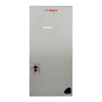
Summarization of Contents
Key to Symbols and Safety Instructions
Key to Symbols
Explains warning symbols and keywords used in the manual.
Safety
Provides important safety precautions and general notices for installation and use.
Nomenclature
Bosch IDS BVA2.0 Model Nomenclature
Explains the model nomenclature for the Bosch IDS BVA2.0 series.
Bosch IDS BOVA2.0 Model Nomenclature
Explains the model nomenclature for the Bosch IDS BOVA2.0 series.
Dimensions
Bosch IDS BVA2.0 Dimensions
Provides dimensional specifications and diagrams for the BVA2.0 indoor unit.
Bosch IDS BOVA2.0 Dimensions
Provides dimensional specifications and diagrams for the BOVA2.0 outdoor unit.
AHRI 210/240 Performance Data
Bosch IDS BOVA2.0 Performance Data
Presents AHRI performance data for Bosch IDS BOVA2.0 outdoor units.
Product Specifications
Bosch IDS BVA2.0 Product Specifications
Details product specifications for the Bosch IDS BVA2.0 indoor unit.
Bosch IDS BOVA2.0 Product Specifications
Details product specifications for the Bosch IDS BOVA2.0 outdoor unit.
Extended Performance Data
Cooling Mode Performance Data
Provides extended performance data for cooling mode with BOVA/BVA combinations.
Heating Mode Performance Data
Provides extended performance data for heating mode with BOVA/BVA combinations.
Layout of Functional Components
3 Ton Component Layout
Illustrates the functional components of the 3-ton outdoor unit.
5 Ton Component Layout
Illustrates the functional components of the 5-ton outdoor unit.
Refrigerant Flow Diagrams
Cooling Operation Flow Diagram
Depicts the refrigerant flow during cooling and oil return operations.
Heating Operation Flow Diagram
Depicts the refrigerant flow during heating and oil return operations.
Control
Crankcase Heater Control
Explains the operation and purpose of the crankcase heater control.
Other Operations
Details unit operations under specific conditions.
Field Settings
Initial Unit Preparation and Installation Checklist
Provides a checklist for initial unit preparation and installation.
Initial Start-up Checklist
Offers a checklist for initial unit start-up procedures.
Dip Switch Settings
Details dip switch settings and configurations.
Check Point Values
Lists system parameters accessible via the check button for monitoring.
Diagnosis and Troubleshooting
Control Board Component Layout
Identifies components on the control boards.
Fault Code and Limited Condition Descriptions
Lists and describes fault codes and limited condition status codes.
Fault Codes and Limited Conditions Troubleshooting
Provides troubleshooting steps for various fault codes.
Situational Troubleshooting
Addresses common operational issues without specific fault codes.
Advanced System Check
Abnormal Pressure Diagnosis
Provides a flowchart for diagnosing abnormal pressure conditions.
Pressure Transducer (PT) Testing
Details how to check and test the pressure transducer.
Electronic Expansion Valve (EEV) Diagnosis
Explains how to diagnose and test the electronic expansion valve.
Temperature Sensor Testing
Guides on checking and testing various temperature sensors.
High Pressure Switch (HPS) Testing
Details how to test the high-pressure switch.
Outdoor Fan Motor Diagnosis
Provides steps for diagnosing and testing the outdoor fan motor.
Indoor Blower Motor Troubleshooting
Guides on troubleshooting and testing the indoor blower motor.
Compressor Check and Test
Details how to check and test the compressor.
System Charge Check and Adjustment
Explains how to check and adjust system refrigerant charge.
Outdoor Board Fuse Check
Guides on checking and replacing the outdoor board fuse.
Indoor Board Fuse Check
Details how to check and replace indoor board fuses.
Appendix
Outdoor Unit Control Board Diagram
Provides a diagram and explanation of the outdoor unit control board.
Indoor Unit Control Board Diagram
Provides a diagram and explanation of the indoor unit control board.
Technical Instructions E-Box Replacement Bosch IDS BOVA
Key to Symbols and Safety Instructions
Explains warning symbols and keywords used in this document.
Components Included in E-Box Kit
Lists the components included in the E-Box replacement kit.
E-Box Replacement Instructions
Provides step-by-step instructions for replacing the E-Box.


Need help?
Do you have a question about the BVA-36WN1-M20 and is the answer not in the manual?
Questions and answers