Advertisement
INSTALLATION MANUAL
Thank you for purchasing a JL Audio TwK™ System
Tuning Processor for your automotive sound system.
This product has been designed and manufactured to exacting
standards in order to ensure years of musical enjoyment in your vehicle.
For maximum performance, we highly recommend that you have your
TwK™ DSP installed by an authorized JL Audio dealer. Your authorized
dealer has the training, expertise and installation equipment to ensure
optimum performance from this product without compromising your
vehicle's functionality. Due to the complexity of modern vehicle systems,
we do not recommend self-installation unless you have extensive
experience in automotive electrical systems. Should you decide to install
this product yourself, please take the time to read this manual thoroughly
to familiarize yourself with its installation requirements
and setup procedures.
If you have any questions regarding the instructions in this manual or
any aspect of the product's operation, please contact your authorized
JL Audio dealer for assistance. If you need further assistance, please contact
the JL Audio Technical Support Department at technical@jlaudio.com
or call (954) 443–1100 during business hours.
Advertisement
Table of Contents

Related Manuals for JL Audio TwK D8


Summarization of Contents
JL Audio TwK™ System Tuning DSPs: Installation Manual
Welcome and Product Introduction
Thanks the user for purchasing and introduces the TwK™ DSP system.
Contacting JL Audio Support
Provides contact details for technical assistance and dealer support.
Important Safety and Usage Guidelines
Hearing Protection Warning
Urges caution regarding high sound pressure levels to prevent hearing damage.
Vehicle Compatibility and Safety
Specifies 12V negative-ground systems and safety considerations for installation.
What's Included and Product Overview
Lists included components and provides a brief overview of the TwK™ DSP's capabilities.
Software Requirement and Installation Planning
TüN™ Software Requirement
States the necessity of TüN™ software for product setup and configuration.
Key Features of TwK™ 88
Details the flexible input design, setup features, equalizers, and outputs.
Planning Your Installation Process
Emphasizes careful planning to avoid damage to vehicle systems and recommends professional installation.
Making Power Connections
Power Connector and Wiring
Explains how to connect wires to the removable power connector plug using set screws.
Critical Power Connection Safety
Warns about correct polarity, wire placement, and securing wires to prevent short circuits.
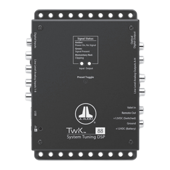
TwK™ Hardware Identification
Top View Component Labels
Identifies key controls and indicators visible from the top of the unit.
Input and Output Panel Layout
Details the layout of power, audio output, and input connection panels.
Detailed Power Connections
Power Connector Pin Assignments
Lists and describes each pin: +12VDC Battery, Ground, +12VDC Switched, Remote Out, Valet In.
Essential Power Connection Safety
Stresses disconnecting the battery and using fuses for safe power connections.
Connecting Audio Inputs and Outputs
Input Signal Options
Describes Line-Level Analog, Optical Digital, and Coaxial Digital input types.
Output Signal Options
Details Analog Outputs and Optical Digital Output for audio signal distribution.
Unit Controls and Status Indicators
Signal Status LEDs Explained
Details the meaning of the signal status LEDs for input and output.
Preset Toggle Button Function
Explains how to use the button to select saved presets.
JLid Port and DRC-200 Controller
Describes the connection and dual rotary/push-button controls of the DRC-200.
DRC-200 Installation and USB Connectivity
Mounting the DRC-200 Control Knob
Provides step-by-step instructions for installing the DRC-200's control knob and LED.
USB Port for Software Interface
Explains the USB port's role in connecting to a PC for software setup and firmware updates.
Troubleshooting Common Issues
Power-On and Volume Problems
Addresses issues like the unit not turning on or experiencing low/no volume.
Technical Specifications
Digital, Electrical, and Input Specs
Details processor, voltage, current, input types, and sensitivity settings.
Output, Remote, and Dimensions
Covers output types, remote control, and physical dimensions of the unit.
Warranty and Service Information
JL Audio USA Limited Warranty
Outlines warranty coverage, exclusions, and transferability for US customers.
Customer Service and Returns
Provides contact details and procedures for warranty service and returns.
TüN™ Software System Requirements
PC System Requirements for TüN™
Lists minimum and recommended PC specifications for running the TüN™ software.
TüN™ Software Functionality
Explains how TüN™ software controls and configures JL Audio DSP products.
TüN™ Software Key Definitions
Understanding Projects, Presets, and Valet
Defines core concepts like PROJECT, PRESET, VALET, and DRC used in the software.
TüN™ Software Interface Layout
New Project Configuration Wizard
Guides through initial project setup, naming, and vehicle information.
Interface Navigation and Workspace
Explains the main interface areas: Setup Tab, Tune Tab, and Workspace Legend.
TüN™ Setup and Tune Tabs
Setup Tab Configuration Areas
Highlights Input, Input Mixer, Equalizers, Router, DRC Setup, and Outputs panels.
Tune Tab Configuration Areas
Highlights Equalizers, Crossovers, Delay/Polarity, and Outputs panels.
Getting Started with TüN™ Projects
Creating a New Project
Steps to initiate a new project and establish baseline parameters.
Project Level Selection
Explains Basic, Advanced, and Expert project levels and their implications.
Configuring Project Settings
Input and Output Configuration
Details selecting input signals and output configurations for the system.
Speaker Distance Entry
Allows setting speaker distances for automatic delay compensation.
Project Management Tools Overview
Describes icons for managing projects: Save, Open, Transfer, Settings.
TüN™ Software Controls and Presets
Valet Mode and Undo/Redo Functionality
Explains Valet mode activation and the undo/redo feature for tuning steps.
Preset Control and Management
Covers managing presets, including channel muting and level meters.
TüN™ Setup Tab: Inputs and Equalizers
Input Settings and Mixer
Configures input sensitivity, connection types, and combines input channels.
Equalizer Bank Assignment
Explains assigning EQ banks to output channels and pre-EQ level trim.
TüN™ Setup Tab: Routing and Outputs
Router Panel Functionality
Establishes signal flow between EQ banks and output channels.
DRC Setup and Output Configuration
Configures DRC-200 controls and renames output channels or digital outputs.
TüN™ Tune Tab: Equalizer Adjustments
Equalizer Controls and Options
Details EQ band reordering, reset, defeat, selection, and linking.
EQ Value Entry and Graphing
Explains numerical entry, frequency, Q, gain adjustments, and real-time graph display.
TüN™ Tune Tab: Crossover Settings
Crossover Filter Definitions
Defines High-Pass, Low-Pass, and Bandpass filters and their parameters.
Filter Frequency and Slope Adjustment
Details adjusting filter frequencies, slopes, and alignment for crossovers.
TüN™ Tune Tab: Advanced Crossover
Filter Frequency and Slope Options
Provides details on advanced filter controls and slope selections.
Passband Display and Analysis
Shows crossover passband response and allows detailed visualization.
TüN™ Tune Tab: Delay and Outputs
Speaker Distance and Delay Settings
Explains setting speaker distance and additional delay for sonic optimization.
Output Level Trim and Labeling
Adjusts relative output channel levels and displays/edits channel labels.
TüN™ Advanced Tuning Features
Control Linking for Simultaneous Adjustment
Allows temporary linking of controls across multiple channels for unified adjustments.
Input Sensitivity Level Setting Guide
Step-by-step guide for setting input sensitivity for optimal signal integrity.
Need help?
Do you have a question about the TwK D8 and is the answer not in the manual?
Questions and answers