JL Audio TwK 88 Installation Manual

JL Audio TwK 88 Installation Manual

System tuning dsps

Advertisement

INSTALLATION MANUAL
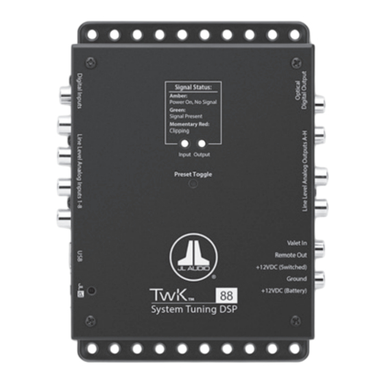
Thank you for purchasing a JL Audio TwK™ System
Tuning Processor for your automotive sound system.
This product has been designed and manufactured to exacting
standards in order to ensure years of musical enjoyment in your vehicle.
For maximum performance, we highly recommend that you have your
TwK™ DSP installed by an authorized JL Audio dealer. Your authorized
dealer has the training, expertise and installation equipment to ensure
optimum performance from this product without compromising your
vehicle's functionality. Due to the complexity of modern vehicle systems,
we do not recommend self-installation unless you have extensive
experience in automotive electrical systems. Should you decide to install
this product yourself, please take the time to read this manual thoroughly
to familiarize yourself with its installation requirements
and setup procedures.
If you have any questions regarding the instructions in this manual or
any aspect of the product's operation, please contact your authorized
JL Audio dealer for assistance. If you need further assistance, please contact
the JL Audio Technical Support Department at technical@jlaudio.com
or call (954) 443–1100 during business hours.

Advertisement

Table of Contents
loading
Need help?

Need help?

Do you have a question about the TwK 88 and is the answer not in the manual?

Questions and answers

Summary of Contents for JL Audio TwK 88

  • Page 1 If you have any questions regarding the instructions in this manual or any aspect of the product’s operation, please contact your authorized JL Audio dealer for assistance. If you need further assistance, please contact the JL Audio Technical Support Department at technical@jlaudio.com...
  • Page 2 Protect Your Hearing! We value you as a long-term customer. For that reason, we urge you to practice restraint in the operation of this product so as to not damage your hearing and that of others in your vehicle. Studies have shown that continuous exposure to high sound pressure level can lead to permanent (irreparable) hearing loss.
  • Page 3 If you are uncomfortable or unfamiliar with reading diagrams or testing signals, please enlist the services of your authorized JL Audio dealer to perform the installation.
  • Page 4 Installation Procedure/Making Connections ™ The TwK uses a removable plug for making power connections. Receptacles in the plug accept up to 16 AWG wire. To attach wires to the plug, use a small flathead screwdriver to back out the set screws. Strip 1/4 inch (6 mm) of insulation from the end of each wire and insert the bare wire into the receptacle, seating it firmly so that no wire is exposed.
  • Page 5 Top View* Power Connections Page 6 Input Connections* Page 7 Output Connections Page 7 Signal Status LEDs Page 8 Preset Toggle Button Page 8 ™ JLid Port and DRC-200 Function Page 8 USB Port Page 9 * TwK ™ 88 pictured. ™...
  • Page 6 Power Connections The TwK ™ has a 5-pin “Power Connector” jack located next to the “Analog Outputs”. The Power Connector jack accepts the removable 5-pin plug and is used to make the connections below. Plug Connection Description +12VDC (Battery) Positive (+12V) Power Connection Ground Negative (GND) Ground Connection +12VDC (Switched) Positive (+12V) Turn-On Input...
  • Page 7 Input Connections For maximum versatility, the TwK ™ 88 is equipped with three methods for connecting input signals. Select the input type that is appropriate for the specific equipment of your audio system. Line-Level Analog Inputs: Eight female RCA jacks accept low-voltage, line- level audio signals, with configurable input sensitivity settings (up to 7.1 V ™...
  • Page 8 Signal Status LEDs Located on top of the unit are two LEDs used to report the signal status of the ™ 88 / D8. Separated by “Input” and “Output”, these LEDs may be referenced during setup and normal use. Refer to the markings above the LEDs for specific behavior condition.
  • Page 9 The USB Port is designed for connection of a PC to your TwK processor using the ™ supplied USB A/B cable. Once connected, you’ll be able to use the JL Audio TüN Software Interface to setup and configure the full functionality of your TwK ™...
  • Page 10: Troubleshooting

    Troubleshooting Problem Possible Cause Possible Solution Remove fuse and check with continuity meter. Faulty fuse Replace if necessary. Check “Ground” and both “+12VDC” connections Twk™ doesn’t Poor connection integrity for pinched wires; ensure tight connections. turn on Make sure there is a sufficient +12V supply at the Insufficient “+12VDC “+12VDC (Switched)”...
  • Page 11: Specifications

    Specifications Digital Specifications Processor Intersil® D2Audio DAE-6 Bit Depth / Sample Rate 24 bit / 48 kHz Electrical Specifications Power Supply Type Regulated DC-DC SMPS Operating Voltage 10 – 16V DC Standby Mode Current Draw < 1.5 mA Operating Current Draw 0.7 A at 13.8V Recommended Fuse Value Recommended Fuse Type...
  • Page 12 Non-defective items received will be returned freight-collect. Customer is responsible for shipping charges and insurance in sending the product to JL Audio. Freight damage on returns is not covered under warranty. For Service Information in the U.S.A. please call...
  • Page 13 Software Overview for use with TwK™ Processors (ver. 2.0)
  • Page 14: System Requirements

    2.56.145 of the TüN™ software. Some details may vary in future updates and releases. Please consult the online help or the support section of the JL Audio website for the most up-to-date information, and for in-depth explanations of the TüN™...
  • Page 15 TwK™ (or other JL Audio products) via the “JLid™ Port” on the JL Audio hardware. The TwK™ 88 and TwK™ D8 each include a DRC-200 controller with indicator LED. This controller has an outer knob and an inner knob, with push-button functionality.
  • Page 16 NEW PROJECT CONFIGURATION Workspace Legend ........Page # TUNE TAB CONFIGURATION NEW PROJECT CONFIGURATION “EQUALIZERS” Panel ......11-12 NEW PROJECT: Project Level..... 6 “CROSSOVERS” Panel ......12-13 NEW PROJECT: Input Configuration ..7 “DELAY/POLARITY” Panel ..... 14 NEW PROJECT: Output Configuration ..7 “OUTPUTS”...
  • Page 17 SETUP TAB CONFIGURATION TUNE TAB CONFIGURATION Page 5...
  • Page 18: Getting Started

    GETTING STARTED To start a New Project, select “Create a New Project” from the Startup Dialog Box or “New Project” from the toolbar on the left side of the interface. Whenever a new PROJECT is created, a New Project Setup Tool window pops up in front of the TüN™...
  • Page 19: Project Management

    Input Configuration: Select from a list of common input signal configurations. The TüN™ software will automatically name the Inputs and configure the Input Mixer. These can be edited later, if needed. Output Configuration: Select from a list of output signal configurations. The TüN™...
  • Page 20: Level Meters

    The rest of the right vertical edge of the dark gray frame is dedicated to status indicators and for TwK™ user controls needed while connected to the PC. Below the JL AUDIO TüN™ logo, you will see a display of the current Project Level (Basic, Advanced or Expert). Below that, you will find connection status indicators.
  • Page 21: Setup Tab

    SETUP TAB “INPUTS” Panel TwK™ 88: Inputs are numbered from 1-8, corresponding to the connection labels on the TwK™ 88 hardware. The adjacent Input Labels can be edited via the PC’s keyboard. Input Settings: click on the “Menu” to access the Input Settings Menu (TwK™...
  • Page 22 the rear speakers. With only two EQ Banks, you can tune the entire eight- channel system. In the Basic PROJECT Level, the EQ Banks are fixed in a full-octave, graphic EQ format that should be familiar to all audio enthusiasts. This provides a fast, simple method for improving system frequency response.
  • Page 23 TUNE TAB “EQUALIZERS” Panel: Reorder: Re-establishes numerical order (1-10) of parametric EQ band labels in order of center frequency, from low to high. (Parametric EQ only) All Reset: Resets all EQ bands to their default values All Off/On: Temporarily defeats/turns on all EQ bands EQ Select: Select an EQ to adjust from the pull-down menu (Linked EQ’s are shown as pairs).
  • Page 24 EQ adjustment with Arrow Keys: You can also select EQ Band Label(s) with your mouse/trackpad, and then make adjustments using the arrow keys on your keyboard. Finer adjustment steps can be achieved by using the SHIFT key, in conjunction with the arrow keys. Keyboard commands: Up/Down Arrows: Boost/Cut Left/Right Arrows: Center Frequency down/up (Parametric EQ only)
  • Page 25 Passband: the range of frequencies uniformly passed by a filter. Defined by two frequencies. Stopband: the range, or ranges of frequencies outside the passband. The TüN™ software provides separate controls for adjusting a High- Pass Filter and a Low-Pass Filter on each Output Channel. These can be combined to create a Bandpass Filter.
  • Page 26 “DELAY/POLARITY” Panel: The TwK™ has a powerful digital delay feature with separate entries for Speaker Distance and Additional Delay, which can apply over 24 feet of speaker distance compensation (21.3 milliseconds of delay) to each of its output channels. Among other things, this delay capability allows you to compensate for the unequal distances between the primary listener and the various speakers installed in the vehicle.
  • Page 27 Repeat for the remaining input channels. Note: When using JL Audio amplifiers, set the amplifier’s Input Sensitivity control to twelve o’clock (noon) and Input Voltage switch (if equipped) to “Low”.
  • Page 28 “JL Audio”, “Ahead of the Curve” and the JL Audio logo are registered trademarks of JL Audio, Inc. • ©2017 JL Audio, Inc. • For more detailed information please visit us online at www.jlaudio.com. Due to our policy of continuous product development, all specifications are subject to change without notice.

This manual is also suitable for:

Twk d8

Table of Contents