Table of Contents
Advertisement
Quick Links
Advertisement
Table of Contents

Related Manuals for METVISA BIMG PCL.22


Summary of Contents for METVISA BIMG PCL.22
-
Page 2: Table Of Contents
TABLE OF CONTENTS 1. Safety Information ........................3 1.1 General Warnings ........................3 2. Technical Features ........................4 2.1 Main Components ........................4 2.2 Technical Data ........................... 5 3. Installation ............................. 6 3.1 Equipment Layout ........................6 3.2 Electrical Connection ......................... 7 3.3 Safety Measures and User Instruction .................. -
Page 3: Safety Information
1. Safety Information 1.1 General Warnings • Cautions / precautions must be observed when installing, using, maintaining and discontinuing use of this equipment; • Before carrying out any operation (assembly, utilization (use), maintenance and reuse after prolonged use of the equipment), read the manual carefully; •... -
Page 4: Technical Features
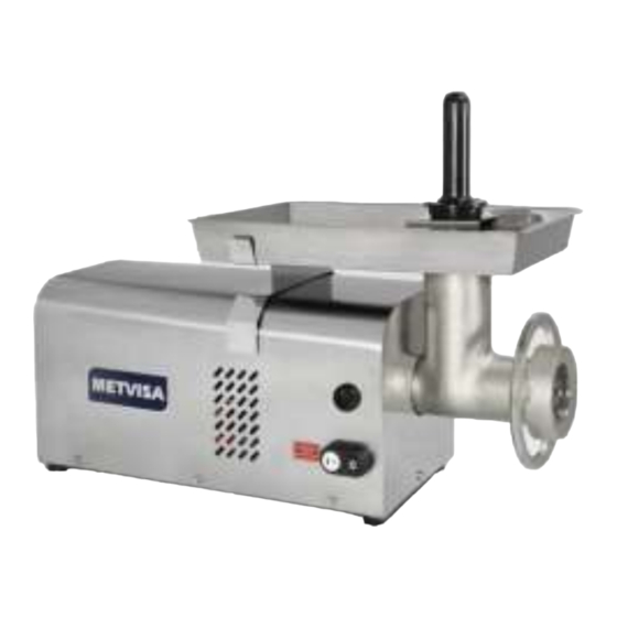
2. Technical Features 2.1 Main Components For the equipment described in this manual, safety in use, cleaning, maintenance and maximum cleaning are guaranteed by the design and special design of all parts and also by using stainless steel and other materials suitable for contact with the food. The equipment was built with the following features: •... -
Page 5: Technical Data
2.2 Technical Data Nominal Use Rated Discs Lubricant Voltage Capacity Measures Model Weight Current (Ø mm SAE140 LengthxHt.xDepth (kg/h) ** (kg) hole) (ml) (mm) * PCI10110M604 280x480x790 30.5 5 or 8 16.4 PCI10220M501 280x480x790 30.5 5 or 8 280x480x790 30.5 5 or 8 PCI10220M502 280x480x790... -
Page 6: Installation
3. Installation 3.1 Equipment Layout The connection to the mains and the arrangement for operation must be carried out by a qualified professional. Check that the voltage of the eqiuipment matches the mains voltage. • In the installation, it is essential to make this manual available to the professionals who will do the same. -
Page 7: Electrical Connection
ATTENTION! The installation and the place where the equipment is to be disposed of must comply with the rules of risk prevention and safety at work (Regulatory standard NR-12 for Brazil or according to the regulation in force in your country). The manufacturer shall not be liable for any direct or indirect damages caused by non- compliance with these standards and other instructions presented in this manual. - Page 8 • Blue plug for 220 V voltage, current up to 16 A. Note: The PCL grinder power supply.98 (MF) 110 V, require a 25 A circuit breaker; PCL.98 grinders (MF) 220 V, require a 16 amp circuit breaker. Already the three-phase grinder (TF) PCL.98 models, are supplied with power cables with industrial type 3P + N + T plugs (3-pole + neutral + ground) for 220 V or 380 V voltages.
- Page 9 The maintenance procedure on the power cable and / or the power plug of the equipment must be carried out by an authorized agent or qualified person. When reassembling these components and making the points connections, you can also use the markings on the inside of the plug in your plastic region as a reference.
-
Page 10: Safety Measures And User Instruction
ATTENTION! Before connecting your equipment, always check that the mains voltage is the same as the voltage of the equipment. If it is not the same, contact the manufacturer or your authorized dealer. The supply voltage of the devices is 110 V (60 Hz) or 220 V (50 or 60 Hz) single phase and 220 V or 380 V (50 or 60 Hz) three phase (PCL.98) as shown on the voltage label attached to the power cable or as indicated on the card data label on the back of the unit (see the figure on this label in item 2.2 of this manual). -
Page 11: Equipment Usage
ATTENTION! If they are rotating clockwise, check that the electrical connection is reversed with respect to the wiring diagram (item 9 - Attachments), refer to the electrical installation instructions in item 3.2 (Electrical Connection) or contact your nearest authorized service center from you. ATTENTION! Operation of the equipment in the wrong direction of rotation may lock in addition to the spool, cross blade and disc. -
Page 12: Operating Procedures
4.3 Operating Procedures Before operating your equipment, disassemble the components (the following instructions) that will come in contact with the meat (pan, socket, grinder nozzle, endless spool, cross blade, discs and nozzle nut) and clean them. Perform cleaning with the equipment disconnected from the mains. Follow the cleaning instructions in item 5 of this manual. - Page 13 • Assembly: The assembly procedure is the reverse of disassembly. When attaching the crosshead blade to the spool pin, make sure the blade side of the blade is facing forward. Before mounting the disc, choose the model (hole Ø 5 or 8 mm) that fits your need at the moment.
- Page 14 • Operation: Before connecting the equipment, make sure that the endless spool is rotating correctly (counterclockwise as per instructions in 3.3), and that the supply voltage of the equipment is in accordance with the mains voltage. Also check that the tray is attached in the holder, the disc is engaged and locked with the nut of the nozzle and the nozzle of the grinder is fixed with the knob.
-
Page 15: Cleaning And Maintenance
ATTENTION! Do not remove the nozzle from the grinder or the tray with the equipment switched on, nor should your fingers, hands or objects (such as spoons and knives) be placed inside the food nozzle as this may cause accidents. Any irregularities please contact the authorized service center nearest you. -
Page 16: Maintenance And Behavior In Case Of Breakdowns
The remainder of the equipment should be cleaned as many times as possible to prevent food residue from drying out and sticking to parts. For cleaning, dilute soap or neutral detergent or ammonia-based remover in warm water and apply with a soft cloth. With a cloth moistened with water, rinse and then wipe the parts with a dry cloth. - Page 17 ATTENTION! Always check the wear of the plastic washer, located on the endless spool, replace it when necessary and never forget to attach it when assembling the nozzle, as working without this item will lead to premature wear of the parts. It is recommended to carry out preventive maintenance every 6 months, checking and adjusting clearances, cleaning internal parts, etc.
- Page 18 When you experience any malfunction or non-compliance, refer your equipment to the nearest service center. See technical assistance in the folder provided with the device or consult the link on our website: www.metvisa.com.br...
-
Page 19: Annexes
6. ANNEXES Electrical Schematic PCI / PCL.10/22 MF - Voltage 110 V or 220 V - 60 Hz – 3/4 HP and 1 HP NOTE:Motor with double direction of rotation. To reverse the rotation, change T5 to T8. -
Page 20: Electrical Schematic Pci / Pcl.10/22 Mf - Voltage 220 V - 50 Hz - 3/4 Hp And 1 Hp
Electrical Schematic PCI / PCL.10/22 MF - Voltage 220 V - 50 Hz – 3/4 HP and 1 HP... -
Page 21: Electrical Schematic Pcl.98 Mf - Voltage 110 V - 60 Hz - 2 Hp
Electrical Schematic PCL.98 MF - Voltage 110 V - 60 Hz - 2 HP NOTE: In the above Electrical Schematic, white wires are represented by pink. Motor with double direction of rotation. To reverse the rotation, change T5 to T8. -
Page 22: Electrical Schematic Pcl.98 Mf - Voltage 220 V - 60 Hz - 2 Hp
Electrical Schematic PCL.98 MF - Voltage 220 V - 60 Hz - 2 HP NOTE: In the above Electrical Schematic, white wires are represented by pink. Motor with double direction of rotation. To reverse the rotation, change T5 to T8. -
Page 23: Electrical Schematic Pcl.98 Mf - Voltage 220 V - 50 Hz - 2 Hp
Electrical Schematic PCL.98 MF - Voltage 220 V - 50 Hz - 2 HP NOTE: Motor with double direction of rotation. To reverse the rotation, change T5 to T8. -
Page 24: Electrical Schematic Pcl.98 Tf - Voltage 220 V - 50 Hz Or 60 Hz - 2 Hp
Electrical Schematic PCL.98 TF - Voltage 220 V – 50 Hz or 60 Hz - 2 HP NOTE: In the above Electrical Schematic, white wires are represented by pink. To invert the rotation, change phase R through phase S. -
Page 25: Electrical Schematic Pcl.98 Tf - Voltage 380 V - 50 Hz Or 60 Hz - 2 Hp
Electrical Schematic PCL.98 TF - Voltage 380 V - 50 Hz or 60 Hz - 2 HP NOTE: In the above Electrical Schematic, white wires are represented by pink. To invert the rotation, change phase R through phase S. -
Page 26: Blown Up Design
Blown up Design... - Page 27 Blown up Design...
- Page 28 Blown up Design...
-
Page 29: Replacement Parts
Replacement Parts Position Code Description Qty. Model BAS104 Assemble Base - PCI/L.10/22 PCI/L.10/22 CJT900 Assemble Base - PCL.98 PCL.98 CRC1234 Base - PCI/L.10/22 PCI/L.10/22 BAS036 Base - PCL.98 PCL.98 PEP004 Rubber Foot PRR015 Mac. Screw Round GEARBOX Assembled Gearbox CRC1387 Gearbox Bottom - PCIL.10/22 PCI/L.10/22 MTE232... - Page 30 Replacement Parts Position Code Description Qty. Model ORG002 PCI.10/22 / PCL.10 2.19 ORG019 O'ring PCL.22 ORG004 PCL.98 PRT056 Allen Screw PCI.10/22 / PCL.10 2.20 PRT055 Allen Screw PCL.22 PRS009 Hexagonal Screw PCL.98 PRT055 PCI.10/22 / PCL.10 2.21 Allen Screw PRT057 PCL.22 BCH069 PCI/L.10/22...
- Page 31 Replacement Parts Positio Code Description Qty. Model CJT356 PCI.10 Complete Head Nozzle - PC.10 CJT038 PCL.10 CJT358 PCI.22 Complete Head Nozzle – PC.22 CJT037 PCL.22 Complete Head Nozzle – PC.98 CJT648 PCL.98 BCA014 PCI.10 Body of the Nozzle – PC.10 BCA003 PCL.10 17.1...
- Page 32 Replacement Parts Position Code Description Qty. Model PTC168 Fixed Nozzle Guard PCI.10/22 PCI.10/22 PTC169 Fixed Nozzle Guard PCL.10/22 PCL.10/22 PTC181 Fixed Nozzle Guard PCL.98 PCL.98 PRS332 Hexagonal Screw Stainless Steel SBT584 Tray Support PCI.10 PCI.10 SBT585 Tray Support PCL.10 PCL.10 SBT586 Tray Support PCI.22 PCI.22...
- Page 33 Notes...
- Page 34 Notes...
- Page 36 IMG-BRASIL Gastronomy Machinery Industry Ltda. CNPJ 11.193.347/0001-14 - CREA 131726-3 Rod. Antônio Heil – KM 23 Nº 5825 – Limoeiro CEP 88352-502 - Brusque – SC – Brazil Phone/fax. +55 47 3251-5555 - Site: www.metvisa.com.br E-mail: sac@metvisa.com.br - export@metvisa.com.br - export2@metvisa.com.br...
Need help?
Do you have a question about the BIMG PCL.22 and is the answer not in the manual?
Questions and answers