Table of Contents
Advertisement
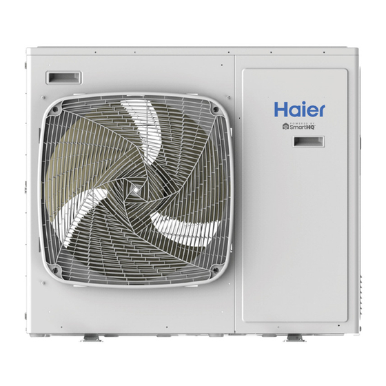
Outdoor Models
Appearances vary by model
• Please read this manual before using the heat pump.
• Keep this user manual for future reference.
Before troubleshooting or servicing
equipment, review equipment installation
met. Including, but not limited to: wiring,
clearance, ducting (where applicable),
power, and line set requirements. Correct
any installation issues before continuing.
Multi-Zone
Ductless Multi-Split Heat Pumps
Indoor Models
Appearances vary by model
Service Manual
Wall Mount - Highwall
2'x2' Compact Cassette
Slim Duct
Mid-Static Ducted
Console
31-5000942 Rev. 0
Advertisement
Chapters
Table of Contents

Related Manuals for Haier GE AW12TC2HDA


Summarization of Contents
Service Manual
Outdoor Models
Overview of outdoor unit models and their appearances.
Indoor Models
Overview of indoor unit models and their appearances.
Introduction
Safety & Precautions
Essential warnings and cautions for safe installation and operation.
Specifications
Detailed technical specifications for various unit models.
Functions and Control
Explanation of system modes, fan control, and operational logic.
Outdoor Units
Components
Identification and overview of outdoor unit parts and their functions.
Operation
Details on cooling, heating, defrost, and EEV control modes.
Service Procedures
Step-by-step instructions for servicing outdoor unit components.
Wiring Diagrams
Electrical schematics for connecting outdoor unit components.
Error Codes
List of outdoor unit error codes and their meanings for troubleshooting.
Highwall Indoor Units
Components
Identification of parts within the highwall indoor unit.
Service Procedures
Instructions for maintenance and repair of highwall indoor units.
Wiring Diagram
Electrical schematic for highwall indoor unit connections.
Error Codes
Troubleshooting guide for highwall indoor unit error codes.
Compact Cassette Indoor Units
Components
Identification of parts within the compact cassette indoor unit.
Service Procedures
Instructions for maintenance and repair of compact cassette units.
Wiring Diagram & DIP Switch Settings
Schematics and DIP switch configurations for compact cassette units.
Error Codes
Troubleshooting guide for compact cassette indoor unit error codes.
Large Cassette Indoor Units
Components
Identification of parts within the large cassette indoor unit.
Service Procedures
Instructions for maintenance and repair of large cassette units.
Wiring Diagram & DIP Switch Settings
Schematics and DIP switch configurations for large cassette units.
Error Codes
Troubleshooting guide for large cassette indoor unit error codes.
Slim Duct Indoor Units
Components
Identification of parts within the slim duct indoor unit.
Ductwork/Grilles
Guidelines for ductwork configurations and installation.
Service Procedures
Instructions for maintenance and repair of slim duct indoor units.
Wiring Diagram & DIP Switch Settings
Schematics and DIP switch configurations for slim duct units.
Error Codes
Troubleshooting guide for slim duct indoor unit error codes.
Mid-Static Ducted Indoor Units
Components
Identification of parts within the mid-static ducted indoor unit.
Ductwork/Grilles
Guidelines for ductwork configurations and installation.
Service Procedures
Instructions for maintenance and repair of mid-static ducted units.
DIP Switch Settings
Configuration settings for DIP switches on mid-static ducted units.
Error Codes
Troubleshooting guide for mid-static ducted indoor unit error codes.
Console Indoor Units
Components
Identification of parts within the console indoor unit.
Service Procedures
Instructions for maintenance and repair of console indoor units.
Wiring Diagram/DIP Switch Settings
Schematics and DIP switch configurations for console indoor units.
Error Codes
Troubleshooting guide for console indoor unit error codes.
Troubleshooting & Reference
Special Functions
Explanation of special operational features like Auto Restart and defrost.
Matching Tables
Tables for matching outdoor and indoor unit combinations.
Resistance Values
Sensor resistance values at different temperatures for testing.
Component Testing
Procedures for testing key unit components like valves and motors.
Refrigeration Diagrams
Diagrams illustrating refrigerant flow for different unit models.
Outdoor Unit Error Codes
List of error codes specific to outdoor units and their causes.
Troubleshooting Flow Charts
Diagnostic flowcharts for identifying and resolving unit issues.
Need help?
Do you have a question about the GE AW12TC2HDA and is the answer not in the manual?
Questions and answers