Advertisement
Quick Links
Advertisement

Related Manuals for The Flame MILANO


Summary of Contents for The Flame MILANO
- Page 1 L OUNGE/TORCH /MILANO Installation and operating instructions...
- Page 2 If you have any questions or concerns, please contact our technical department. Any additional information is available online at www.theflame.at The Flame is a well-known manufacturer of heating equipment in both Austria and Europe. Our products are manufactured based on strict standards. Each garden heater manufactured...
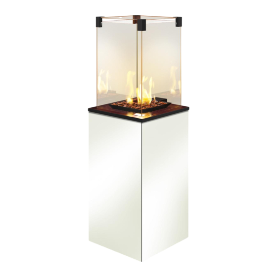
- Page 3 The LOUNGE/TORCH garden gas heater has been designed to be supplied with propane or a mixture of propane butane gas. This device is available in several versions depending on the control options, glazing type and colour preferences.
-
Page 4: Installation
INSTALLATION Your device has been designed to work with gas and pressure type according to the informa- tion table below. Do not use other types of gas or gases with different pressures than those listed below! THIS HEATER MUST BE INSTALLED AND/OR SERVICED BY A QUALIFIED SPECIALIST. DO NOT TAKE ANY ATTEMPT TO MODIFY THE STRUCTURE OF THE DEVICE OR ITS COMPONENTS. -
Page 5: Installation Introduction
• Steel body with wheels. • 0.6 m hose with reducer and anti-tilt safety valve. The LOUNGE/TORCH/MILANO gas garden heater is designed for your comfort; therefore there are two control options: manual control and wireless remote control. The device is equipped with a modern gas control system to prevent uncontrolled gas leaks. -
Page 6: Rules For Installation
The device has an open combustion chamber without the option of connecting it to a flue duct. The LOUNGE/TORCH/MILANO heater is sold with a pre-installed gas control system, but before using it for the first time it is advisable to check the tightness of the system for possible leakage occurred in transport. - Page 7 PLACE. REQUIREMENTS REGARDING SPACE AROUND THE HEATER FREE FROM FLAMMABLE MATERIALS The LOUNGE/TORCH/MILANO garden gas heater has been tested and approved for heating open or well ventilated areas, subject to keeping safe distance from flammable materials, as shown in the diagrams below.
- Page 8 CAUTION!!! The anti-tilt valve is a safety device against overturning of the device, so that when the device over- turns, the valve automatically cuts off the gas supply to the controller and this extinguishes the flame. Fig. 8. CAUTION!!! The connection to the gas source should only be made when the heater is off and the cylinder valve is closed.
-
Page 9: Remote Control
Keep the device in a dark place to exclude measurement errors related to the direct sunlight. LOUNGE/TORCH/MILANO free-standing garden heaters in option with the GV60 module are equipped with a gas control system allowing the user to remotely fire the device and have full control over it. - Page 10 Contact a service technician if the knobs are locked. The LOUNGE/TORCH /MILANO heater uses modern B6R-H9 remote controls set in accordance with the European standard to 868 MHz radio frequencies. The remote control does not require a new transmission code and is ready for use.
- Page 11 USER MANUAL OF THE 6-SYMBOL B6R-H9 CONTROL UNIT Child Proof Hour box Minute box Battery indicator Sleep Thermostat tiimer mode Programmable mode Temperature Fahrenheit or Celsius User manual of the 6-symbol B6R-H9 control unit To change the temperature unit, simultaneously press the buttons.
- Page 12 Child Proof Enabling: To activate the Child Proof function press the buttons. The display shows the icon. Disabling: To deactivate the Child Proof function press the buttons. The icon will disappear. Manual mode Lighting the fire in the fireplace with a single button (default setting) •...
- Page 13 Adjusting the height of the flame To increase the height of the flame, press and hold the button. To reduce the height of the flame or put the fireplace into the standby mode, press and hold Setting the minimum and maximum height of the flame...
- Page 14 Modes Thermostat mode The room temperature is measured and compared with the temperature set on the thermostat. The flame height is automatically adjusted so as to reach the set temperature. Programmed mode Programmes 1 and 2 can be freely modified. You can set the time on and off of...
- Page 15 If the room temperature is lower than the preset, the flame height is reduced to a minimum for a long period of time. One cycle takes approxima- tely 20 minutes.
- Page 16 Disabling the programmed mode 1. Press the button or the button, or the button to go to the manual mode. 2. Press the button, to go to the Thermostat mode. Information: Entering the switch-on temperature of the thermostat will automatically set the same value for the switch-on temperature of the programmed mode.
- Page 17 Switching off time settings (Programme 1) Wybrano opcję „ALL” 12. The display shows , 1 , „OFF”, then for a while you will see the „ALL” symbol. Subsequently, the hour will begin to flash. 13. Set the hour using the buttons.
-
Page 18: Replacement Of Batteries
REPLACEMENT OF BATTERIES Batteries in the receiver, remote control or the power supply module can overheat, spill or even cause an explosion. Do not use batteries that have been exposed to the sun, moisture, heat or vibration. Install only batteries of the same type and the same manufacturer. Do not install new batteries with worn ones. - Page 19 1 minute (time needed to cool down the thermocouple). Flame/gas flow regulation: Adjust the flame using the Temperature Knob B. To adjust the flame and power of the device, manu- ally turn the Temperature Knob B counter clockwise (increase flame) or clockwise (decrease flame).
- Page 20 (item 1.), gas flows to the control burner. (Item 2.) Low flame The ON/OFF knob is in the ON position. The Temperature Knob used to adjust the flame is turned in the clockwise direction. Gas flows through the ON/OFF valve. (Item 3)
- Page 21 The ON/OFF knob is in the ON position. The Temperature Knob used to adjust the flame is turned in the counter clockwise direction. Gas flows through the ON/OFF low flame valve (item 3) and the high flame modulation valve (item 4).
- Page 22 Checklist: Range Activities Carry out the firing procedure in the heater. Verify the correct operation of all the safety systems. Make sure the main burner flame is stable. Make sure the main General burner is burning evenly. inspection Make sure the batteries in the receiver and in the remote control do not need to be replaced (automatic gas control system only) Verify that all modes in the remote control are working correctly (automatic gas control system only)
-
Page 23: Environmental Protection
Verify that the components of the control system are not exposed to overheating. Make sure the ornamental elements do not require cleaning. Make sure the ornamental elements do not touch the glass. Ornamental elements Make sure the ornamental elements do not cover the air openings of the heater furnace. - Page 24 Abb. 1 Maßzeichnung des Heizgerätes TORCH Рис.1. Схема нагревателя TORCH с размерами Fig. 1. Dibujo dimensional de la estufa TORCH / LOUNGE Disegno 1. disegno quotato del riscaldatore TORCH / LOUNGE Dessin 1. Dessin coté du chauffage TORCH / LOUNGE...
- Page 25 Rys. 2. Kółka z hamulcami ułatwiające przemieszcza- nie i bezpieczne ustawianie urządzenia. Fig. 2. Wheels with brakes to facilitate movement and secure positioning. Abb. 2 . Räder mit Bremsen, die die Verbringung und sichere Aufstellung der Anlage erleichtern. Рис.2. Колеса с блокираторами для облегчения движения и надежной фиксации в стационарном положении.
- Page 26 Abb. 3 Minimaler freier Bereich von leichtentzündlichen Stoffen/Gegenständen Рис.3. Регулируемые кронштейны Fig. 3. Distancia mínima libre de materiales inflamables Fig. 3. Distanza minima libera da materiali infiammabili Figure 3 : Espace libre minimal par rapport aux matériaux/objets inflammables Rys. 4. Minimalna wolna przestrzeń od materiałów/przedmiotów łatwopalnych Fig.
- Page 27 TORCH/ LOUNGE na pilota TORCH/ LOUNGE remote control Gaz odniesienia / Gas type / Bezugsgas / Газ отнесения / Referencia del gas / Tipo di gas / Gaz de référence Kategoria urządzenia / Category / Katego- rie der Anlage / Категория оборудования...
- Page 28 TORCH / LOUNGE G30/G31 G30/G31 3B/P(50) 3+(30/37) 3P(30) 3P(37) 3P(50) 3B/P(30) 3B/P(37) 3B/P(50) 3+(30/37) BE, CH, CY, BE, CH, CY, BE, CH, CY, BE, CY, CZ, DK, CZ, ES, FR, CZ, ES, FR, CZ, ES, FR, AT, CH, EE, ES, FR, GB,...
- Page 29 UŁOŻENIE KAMIENI OZDOBNYCH NA PALNIKU Właściwa instalacja kamieni ozdobnych na ogrzewaczu TORCH. LOCATION OF ORNAMENTAL STONES ON THE BURNER Proper installation of the ornamental stones on the TORCH heater. VERTEILUNG DER DEKORSTEINE AUF DEM BRENNER Richtige Installation der Dekorstein auf dem Heizgerät TORCH. РАСПОЛОЖЕНИЕ...
- Page 30 DEMONTAŻ I WYMIANA SZYB/ŚCIAN: Przed przystąpieniem do demontażu ścian i szyb urządzenia, upewnij się, że urządzenie jest wyłączo- ne i wychłodzone, a dopływ gazu jest zamknięty! Okres potrzebny na wychłodzenie najgorętszych elementów urządzenia to ok. 60 minut. Nie dotykaj szyb, ani górnych elementów obudowy przed upływem godziny od momentu wyłączenia urządzenia.
- Page 31 TORCH version, where a hinged door is installed. It is a necessary condition for placing the 11 kg cylinder in the LOUNGE heater, dictated by the size of the device and the cylinder itself.
- Page 32 M NI-Version mit einer abnehmbaren Tür ausgestattet, im Gegensatz zur Standard-TORCH-Version, bei der eine Flügeltür eingebaut ist. Sie ist eine notwendige Voraussetzung für die Platzierung des 11 kg schweren Zylinders im LOUNGE-Heizgerät, die durch die Größe des Geräts und des Zylinders selbst vorgegeben ist.
- Page 33 Krok 2. Zdejmij szklaną pokrywę wraz z zaczepami, a następnie zdejmij maskownicę ścian bocz- nych. Step 2. Remove the glass cover with the clips, and then remove the side wall covers. Schritt 2. Entfernen Sie den Glasdeckel zusammen mit Halterungen, und entfernen Sie dann den Abschlussdeckel der Seitenwände.
- Page 34 Krok 3. Odchyl ściany boczne lekko do siebie, a następnie unosząc je do góry, wyjmij je z otwo- rów mocujących. Step 3. Tilt the side walls slightly from each other and then lift them upwards, removing them from the mounting holes. Schritt 3.
- Page 35 Krok 4. Poluzuj śruby listew dociskowych szyb i wyjmij szyby. Step 4 Loosen the screws of the glass pressure strips and remove the glass. Schritt 4. Lösen Sie Druckleistenschrauben der Scheiben und nehmen Sie die Scheiben heraus. Шаг 4. Ослабьте винты прижимных планок и снимите стекло. Paso 4.
- Page 36 Reduktor ciśnienia gazu Gas pressure reducer Gasdruckregler Iskrownik Редуктор газа Magneto Zündmagnet Reductor de presión de gas Zündmagnet Riduttore di pressione del gas Пьезоэлемент Régulateur de pression du gaz Magneto Zawór przechyłowy odcinający Magneto Accenditore Shut-off tilt valve Magneto Absperrkippventil Sparkle Клапан...
- Page 37 Reduktor ciśnienia gazu Gas pressure reducer Reductor de presión de gas Gasdruckregler Riduttore di pressione del gas Редуктор газа Régulateur de pression du gaz Iskrownik Magneto Zündmagnet Zawór przechyłowy odcinający Zündmagnet Shut-off tilt valve Пьезоэлемент Absperrkippventil Magneto Клапан наклона Magneto Accenditore Válvula de inclinación de cierre Magneto Valvola basculante di intercettazione...
- Page 38 Rys. 8. Zawór antyprzechyłowy, instalowany w urządzeniu. Fig. 8. Anti-tilt valve installed in the device. Abb. 8. Das in der Anlage installierte Anti-Kipp-Sicherheitsventil. Рис. 8. Установленный клапан наклона. Fig. 8. Válvula anti-vuelco instalada en el dispositivo. Fig. 8. Valvola antiribaltamento installata nell'apparecchio. Fig.
Need help?
Do you have a question about the MILANO and is the answer not in the manual?
Questions and answers