
Related Manuals for The Flame Endless effect burner 50


Summary of Contents for The Flame Endless effect burner 50
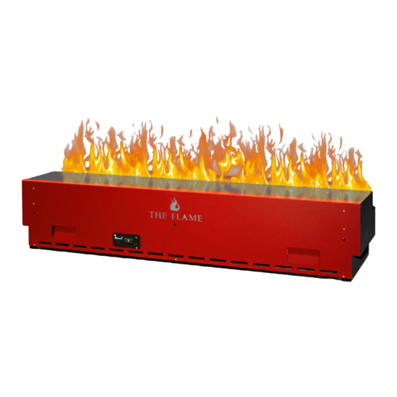
- Page 1 Endless effect burner Continuous, individual, ENDLESS EFFECT FIRE - even around corners. ENDLESS EFFECT FIRE can be realized in any length (at least 100 cm).
- Page 2 Endless effect burner Models Endless effect burner Endless effect burner 50 Endless effect burner 100 Endless effect burner 150...
- Page 3 Endless effect burner Dimensions Endless effect burner 50 Endless effect burner 100 Endless effect burner 51,1 28,2 102,2 28,2 Depth with Depth with open service open service load: 52 cm load: 52 cm Endless effect burner 150 Due to its construction, each burner is suitable for installation around corner, as polygon or round.
- Page 4 Endless effect burner Components for Endless effect burner sump incl. ultrasonic irrigator jets (sump) sump holder membrane and fluidmatic P. Nr.: XLDL incl. fan P.No. SUMPFLFUID P.No. XLSV air filter P.No. XLLF Optional: connection control cable light strip incl. wiring P.No.
- Page 5 Endless effect burner Components for Endless effect burner 1 housing with fire slot 2 service load 3 control panel 4 handles for opening 5 ventilation slots 6 light strip incl. cable harness 7 sump holder incl. fan 8 air filter 9 halogen spots 10 technical unit (sump incl. ultrasonic membrane) 11 plug-on nozzle (sump) 12 water tank for the manual...
- Page 6 Endless effect burner Preparing the End- less effect burner for installation in a THE FLAME Endless Fire Box or similar. 1 Open the service load at the intended position handles. 2 Remove the tanks for the manual filling. Pay attention for a firm stand! Tipping! 3 Now turn the two upper, side, red handles (left and right...
- Page 7 Endless effect burner Preparing the End- less effect burner for installation in a THE FLAME Endless Fire Box or similar. 5 All plug connections must be removed from the sump. 6 Remove the plug from the control cable. Open the two screwdrivers on the plug by turning clock- wise.
- Page 8 Preparing the End- less effect burner for installation in a THE FLAME Endless Fire Box or similar. 8 Close the valve of the piping unit inlet by turning clock- 9 Now turn the two lower, side, red handles (left and right wise by 90 °.
- Page 9 Preparing the End- less effect burner for installation in a THE FLAME Endless Fire Box or similar. 13 The piping unit feed can also be used without a puller 12 The piping unit inlet is now separated from the sump.
- Page 10 Endless effect burner Installation options for the Endless effect burner in a THE FLAME Endless Fire Box 16 Front-mounting option 17 Front-mounting option (cut) Endless Fire Box (flange flush, flange protruding). 18 Tunnel mounting option 19 Tunnel mounting option (cut) Endless Fire Box (flange flush, flange protruding).
- Page 11 Endless effect burner Installation options for the Endless effect burner in a THE FLAME Endless Fire Box 20 2-sided mounting option 21 2-sided mounting option (cut) Endless Fire Box (flange flush, flange protruding). 22 3-sided mounting option (long-short-long) 23 3-sided mounting option (long-short-long) (cut) Endless Fire Box (flange flush, flange protruding).
- Page 12 Endless effect burner Installation options for the Endless effect burner in a THE FLAME Endless Fire Box 24 3-sided mounting option (short-long-short) 25 3-sided mounting option (short-long-short) (cut) Endless Fire Box (flange flush, flange protruding). Glass cover 26 Standalone mounting option 27 Standalone mounting option (cut) Endless Fire Box with base (flange flush, flange pro- truding).
- Page 13 Endless effect burner Installation options for the Endless effect burner in a THE FLAME Endless Fire Box 28 Preparation (on site) manual filling: 1 flexible power cable with current line plug and power connection 230 V Preparation (on site) fully automatic filling: 29 Connection 2 Osmosis water pipe from the O-Box (drawn in the Manual filling: empty pipe), min.
- Page 14 Please note that effect fire systems are supplied with effect burner in clean, purified air only. In the presence of chlorinated or salty air (e.g. pool, sea, etc.), the system must be a THE FLAME tightly shielded from the ambient air. Fresh, clean air Endless Fire Box must be supplied mechanically from below. The fan of this external supply air must be speed controlled.
- Page 15 Endless effect burner Assembly for the Endless effect bur- ner in a THE FLAME Position of the Endless effect burner Endless Fire Box in the Endless Fire Box: symbolic image Example: Endless Firebox 200/230 - 3-sided (short-long-short) with 2 pcs. Endless effect burner 100 1 position for burner 1 2 position for burner 2 For further burners continue ascending to the right.
- Page 16 Endless effect burner Installation for the O-Box fully automatic ope- ration (Fluidmatic) in combination with O-Box. Requirement of it is the preparation of the cables from the O-Box. See the installation and assembly instructions 35 1 Cover (simple) - black, without stones 36 Put the 5-pin power and control cable (coming from the from O-Box.
- Page 17 Endless effect burner Installation for the fully automatic ope- ration (Fluidmatic) in combination with O-Box See the installation and assembly instructions from O-Box. 39 Put the bio-fluid-cable (coming from the O-Box) at the 40 If your system is equipped with several burners, then put backside through the opening from the Endless Fire the Bio-Fluid-cable with a T-piece until the next burner.
- Page 18 Endless effect burner Installation for the fully automatic ope- ration (Fluidmatic) in combination with O-Box 43 Correct position of the power and control cables 1, and 44 Open the front drawer of the Endless Fire Box and re- the Bio-Fluid line 2 move all front burner brackets.
- Page 19 Endless effect burner Installation for the fully automatic ope- ration (Fluidmatic) in combination with O-Box 48 Now lead the power and control cable (connecting cable to the O-Box) with the standard round plug (female) first, 47 1 Few more steps are necessary in this area. which is located to the left of the burner, from behind 2 That area behind the effect burner must be free through the opening into the housing of the Endless from the cable at this time.
- Page 20 Endless effect burner Installation for the fully automatic ope- ration (Fluidmatic) in combination with O-Box 52 Connect the Bio-Fluid line to the marked connection 51 Put the left sided Bio-Fluid-cable from the backside “Osmosis IN” until the stop is felt. Open the blue valve. through the opening in the casing from the Endless If your system has only one burner please continue at effect burner (left, bottom).
- Page 21 Endless effect burner Installation for the fully automatic ope- ration (Fluidmatic) in combination with O-Box 55 Put the connection control cable (right side of the bur- 54 1 Few more steps are necessary in this area. ner) with the standard round-plug (male) from the backside in the case of the Endless effect burner (back, right, down).
- Page 22 Endless effect burner Installation for the fully automatic ope- ration (Fluidmatic) in combination with O-Box 58 Close the service drawer of the Endless effect burner 59 Optionally , the Endless effect burner can be screwed again. Position it in relation to the holes in the front bur- into the Endless fire box. The fixing points are marked. ner mountings and push the Endless effect burner all To do his, open the service drawer.
- Page 23 Endless effect burner Installation for the fully automatic ope- ration (Fluidmatic) in combination with O-Box 62 1 Few more steps are necessary in this area. 63 Please pay attention that the cables are freely accessible 2 That area behind the effect burner must be free behind the burner. Push the burner to the right side. from the cable at this time.
- Page 24 Endless effect burner Installation for the fully automatic ope- ration (Fluidmatic) in combination with O-Box 66 With a turn right the cable can be fixed. 67 Put the second Bio-Fluid cable ending backwards through the opening from the Endless effect burner housing. (left, down) . 68 The Bio-Fluid cable tack in the connection “Osmosis IN”. 69 Correct position of the power and control cables 1, and Please pay attention that the valve is open.
- Page 25 Endless effect burner Installation for the fully automatic ope- ration (Fluidmatic) in combination with O-Box Installation for the 70 When stringing together several Endless effect burners 71 Close the service drawer of the Endless effect burner manual operation the flow part has to be removed at the contact points again.
- Page 26 Endless effect burner Installation for the fully automatic ope- ration (Fluidmatic) in combination with O-Box If your system is equipped with several burners, then repeat the points 61 to 74 by all burners! 74 Now the Endless effect burner can be fixed with the Installation for the Endless Effect Fire Box. The fixing points are signed.
- Page 27 Endless effect burner Installation from the halogen spots, sump and water tank 75 Now insert the halogen spots in the light bar. For a per- 76 The sump can be connected with the water connection. fect colour sequence mix the spots. Perform this pro- Please pay attention that the tube is inserted up to the cedure on all Endless effect burners in your system.
- Page 28 Endless effect burner Installation from the halogen spots, sump and water tank 79 Open the Bio-Fluid-cable valve with a turn against clock- 80 Plug in the plug for the control cable again. wise for 90°. 82 Please pay attention for a fine cable position. The cable 81 Turn the both spin sticks on the plug. are not allowed to get through the burner, so that the service load can easily closed.
- Page 29 Endless effect burner Installation from the halogen spots, sump and water tank 83 With an automatic filling system from the O-Box the wa- 84 If your system works manual than fill all the water tanks ter tanks can be set in or they can be stored elsewhere. with the Bio-Fluid or the distilled water. Close the ser- Close the service loads from the Endless effect burners. vice loads from the Endless effect burners. Tank cap Closing the tank with the screw cap must be done very carefully and with normal, light force.
- Page 30 Endless effect burner Inserting the cover or stone cover 85 1 cover (simple) – black, without stones 86 When use as a stone cover the lava décor stones 2 stone cover (turned cover) – with stones Place the cover or the stone cover in the Endless Fire now can be filled in.
- Page 31 Endless effect burner Assembly of the glass cover 89 Unscrew all Endless Fire Box glass mounting cylinders. 90 Remove one PVC washer. Thus, a PVC washer remains behind the glass and one is placed in front of the glass. 91 Using glass suction, lift the glass cover carefully onto 92 Place one PVC washer on each glass holder and retighten the glass holder.
- Page 32 Endless effect burner Connection with the O-Box 1 O-Box housing with all connections prepared for the installation 2 reverse osmosis system with pump 3 water tank / container 4 control cabinet 5 3/2 way solenoid valve (flushing / filling the burner) 6 supply lines (fresh water) 7 Wastewater is guided in the outflow 8 osmosis compound to the...
- Page 33 Endless effect burner Commissioning the Endless effect burner in the Endless Fire Box 93 As soon as the O-Box is in operation or the plug has 94 To turn on the Endless effect burner please switch the been connected to the power supply with manual operation, the Endless system is ready for operation. main control to “I“...
- Page 34 98 Turn the wheel to the desired level. Wait a few seconds until the desired flame effect is obtained. If the flame is too high, the glass starts 97 After about 45 min. you can set the desired flame inten- to fog. Therefore, the flame must be set sity as the device has reached the full operating tem- smaller until no more fitting is obtained.
- Page 35 Endless effect burner Coupling and controlling with the wireless touch remote control 99 When the Endless effect burner is turned on. The LED 100 To pair with the touch remote, press the RESET button on the built-in receiver will turn red. twice in a row. The LED will start flashing blue additi- onally. 101 Then press the ON/OFF switch on the wireless touch 102 To reset the remote control, press the RESET button remote control.
- Page 36 Endless effect burner Coupling and controlling with the wireless touch remote control 99 When the Endless effect burner is turned on. The LED 100 To pair with the touch remote, press the RESET button on the built-in receiver will turn red. twice in a row. The LED will start flashing blue additi- onally. 101 Then press the ON/OFF switch on the wireless touch 102 To reset the remote control, press the RESET button remote control.
- Page 37 Endless effect burner Discharging the overflowed/spilled Bio-Fluid from the collecting vessel 103 In case of possible sump filling, leakage or spillage of 104 To unload, open the Endless Fire Box drawer and the Bio-Fluid, it flows into a safety basin under the sump. Endless effect burner’s service load. Bio-Fluid can now The O-Box switches off automatically (EMERGENCY- simply be drained off at the valve “Saftey Drain OUT”...
- Page 38 For general cleaning, always use a soft, clean dust cloth, without using scouring agents. Please use “CLEAN” from THE FLAME to clean the sump with the steam out- let nozzle. When cleaning off collected dust deposits and fluff, occasionally a vacuum cleaner with a soft brush attachment can be used to clean the outlet grill for the 105 For cleaning, please use “CLEAN”...
- Page 39 Endless effect burner Maintenance and cleaning 108 Now turn the two upper, side, red handles (left and right 109 Now the plug-on nozzle can be removed from the on the plug-on nozzle) to the outside in order to be able technical unit (sump).
- Page 40 Endless effect burner Maintenance and cleaning 112 All plug connections must be removed from the sump. 113 Remove the plug. Open the two screwdrivers on the plug by turning against clockwise. 114 Remove the plug-on nozzle from the sensor cable. 115 Close the valve of the piping unit inlet by turning clockwise by 90 °.
- Page 41 Endless effect burner Maintenance piping unit open and cleaning piping unit closed 116 Now turn the two lower, side, red handles (left and right 117 Valve on the piping unit inlet open (top) and closed on the sump holder) outside around the sump. (bottom).
- Page 42 Endless effect burner Maintenance and cleaning 120 The piping unit feed can also be used without a puller from the sump connector by pressing the fuse ring 121 Now the sump can be lifted up from the burner. Keep e.g. press down with the fingernail, unlock and pull the the sump as level as possible to prevent water from sump with the Bio-Fluid line at the same time.
- Page 43 Endless effect burner Maintenance and cleaning 125 Replace the nozzle on the technical unit (sump) and 124 Wipe the lamps over with a damp cloth. secure the upper red locking device on both sides. 127 Set in the sump and turn the both red handles (left and 126 The sump can be connected with the water connection.
- Page 44 Endless effect burner Maintenance and cleaning 128 Plug the Cinch-plug again in the sensor line. 129 Open the Bio-Fluid-cable valve with a turn against clock- wise for 90°. 130 Plug in the plug for the control cable again. 131 Turn the both spin sticks on the plug.
- Page 45 Endless effect burner Maintenance and cleaning 132 Please pay attention for a fine cable position. The cable 133 With an automatic filling system from the O-Box the are not allowed to get through the burner, so that the water tanks can be set in or they can be stored else- service load can easily closed.
Need help?
Do you have a question about the Endless effect burner 50 and is the answer not in the manual?
Questions and answers