Table of Contents
Advertisement
Quick Links
Advertisement
Table of Contents

Related Manuals for Sicma BH 120


Summary of Contents for Sicma BH 120
- Page 1 Tiller 100•120•145 USE AND MAINTENANCE MANUAL ORIGINAL INSTRUCTIONS...
- Page 2 BH Tiller - 2 -...
-
Page 3: Table Of Contents
Summar y INTRODUCTION SOME NOTES REGARDING THE USER MANUAL DECLARATION OF CONFORMITY LIST OF RESIDUAL RISKS DELIVERY LETTER TILLER IDENTIFICATION AND MANUAL CODE GENERAL DELIVERY NOTES DECLARED USE TERMINOLOGY OF MAIN PARTS SETUPS SAFETY DEFINITIONS (UNI EN ISO 12100-1:2009) CONVENTIONAL SYMBOLS SAFETY PROVISIONS OPERATOR REQUISITES CLOTHING AND PPE... - Page 4 12.1 COUPLING TORQUE TABLE 12.2 TROUBLESHOOTING TABLE 12.3 MAINTENANCE TABLE SPARE PARTS WARRANTY BH Tiller - 4 -...
-
Page 5: Introduction
Congratulations on your purchase of the BH Tiller The BH Tiller is manufactured by SICMA S.p.A, which has been producing agricultural machines for over 40 years. The BH Tiller has all safety and quality requisites required for this type of equipment. -
Page 6: Declaration Of Conformity
The machine is delivered accompanied by the following Declaration of Con- formity. EC DECLARATION OF CONFORMITY The company Sicma s.p.a. - C.da Cerreto, 39 - 66010 Miglianico (Ch) - Italy Tel.: +39 0871 95841 - Fax: +39 0871 950295 e-mail: info@sicma.it - http://www.sicma.it hereby declares that:... -
Page 7: List Of Residual Risks
LIST OF RESIDUAL RISKS Even though SICMA has done everything possible to be in line with state- of-the-art safety and in compliance with all Directives, Laws and Standards in force, some residual risks still exist: • CUT/CRUSHING HAZARD DUE TO CONTACT WITH TOOLS (rotor) •... -
Page 8: Delivery Letter
(see Chapter 4 "Technical Features”) and the drawings and any other document delivered along with the tiller are the property of SICMA, which reserves all rights and reminds that they cannot be made available to third parties without its written approval. -
Page 9: Tiller Identification And Manual Code
The identification code of this manual is written on the cover. Write the number in a way so that if this manual is lost or damaged, another copy can be requested from SICMA or the nearest dealer by also stating the serial number visible in the marking. Tiller 100•120•145... -
Page 10: General Delivery Notes
• there is no damage to the tiller or accessories • in the event of damage or missing pieces, inform the SICMA or its area representatives, the carrier or its insurance immediately in detail and/ or with photos •... -
Page 11: Declared Use
DECLARED USE The BH Tiller has been designed expressly to work land and has been de- veloped with the sole purpose of loosening, turning and oxygenating the land in order to prepare it for sowing. It has been manufactured to be coupled to tractors that can support the weight of the tiller, with hydraulic lifting device and universal three point hitch and to be activated by the tractor PTO via Cardan transmission. -
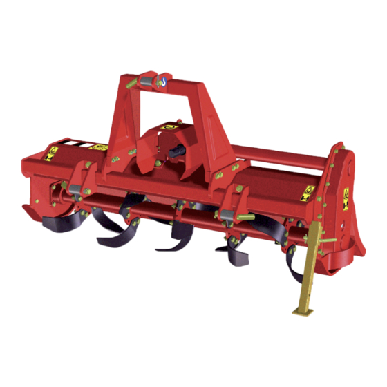
Page 12: Terminology Of Main Parts
TERMINOLOGY OF MAIN PARTS Chassis Lower 3-point hitch Upper 3-point hitch Cardan shaft protection 3-point hitch mast Rotor Hoes Side skids Drive sump Bonnet Stabilization foot SETUPS Amount of hoe kits BH tiller can be equipped with 4 curve hoes per flange or 6 curve hoes per 4 hoes/ 6 hoes/ flange. flange flange Machine Left hoe code 4811786 RIGHT Lh RIGHT Lh Right hoe code 4811785... -
Page 13: Safety
SAFETY During consultation of this use and maintenance manual and on the equip- ment itself, it is possible to find several symbols whose meanings are illus- trated below. DEFINITIONS (UNI EN ISO 12100-1:2009) DANGER: A potential source of physical injury or damage to health. DANGEROUS AREA: Any area within and/or in proximity of a machine in which the presence of a person constitutes a risk for the safety and health of the same. -
Page 14: Conventional Symbols
CONVENTIONAL SYMBOLS ATTENTION GENERAL HAZARD Informs the staff assigned that the operation described has the risk of physical injury if not performed with respect to the Safety Standards. NOTE Informs the staff assigned of information whose content is of relevant con- sideration and importance. -
Page 15: Safety Provisions
SAFETY PROVISIONS Even though SICMA has applied all possible safety devices on the equip- ment, it must be remembered that it can be dangerous for health if not used correctly. It is therefore advised to read and comply with the safety prescrip- tions listed below. -
Page 16: How To Use The Machine
The machine is usually used during the day. If night-time use is excep- tionally requested or use in conditions of reduced visibility, a tractor lighting system or an auxiliary lighting system must be used. • Any arbitrary modification made on this machine lifts Sicma from any responsibility for damage or injuries that could result to operators, third parties or to objects. •... -
Page 17: Reasonably Predictable Incorrect Use
• work on ground with gradient over 3°. Sicma declines any liability for accidents deriving from the failure to comply with the prescriptions indicated below. Given the particular stress to which the equipment is subjected and for safe- ty reasons, if pieces are replaced, only use original spare parts. -
Page 18: Position Of Pictograms On The Machine
2.10 POSITION OF PICTOGRAMS ON THE MACHINE BH Tiller - 18 -... -
Page 19: Safety Pictograms
SAFETY PICTOGRAMS 4781029 CAUTION Tiller Read all instructions and safety rules 4780001 1000 BH120 carefully before using the machine. CE MARKING PLATE 00659 2013 Stop engine and remove key before 144 Kg starting maintenance or repairs. 540 rpm 1000 4781011 FOOT INJURY HAZARD 4783005 Rotary tools: keep a safety distance... -
Page 20: Unloading And Unpacking The Tiller
UNLOADING AND UNPACKING THE TILLER CAUTION Qualified staff that has read and understood the safety prescriptions must unload the tiller from the lorry and handle the equipment in the ATTENTION CRUSHING work place. HAZARD A person in charge of operations must always be present during loading and unloading. -
Page 21: Tiller In Wooden Crate
ATTENTION CUTTING HAZARD If the tiller arrives wrapped in protective film, wear suitable gloves and use a cutter to remove the cellophane, paying attention not to injure the hands or damage the tiller itself. ATTENTION CUTTING HAZARD ATTENTION POLLUTION HAZARD Once the tiller has been unpacked, do not disperse the casing in the en- vironment but contact a specialised agency for its withdrawal. -
Page 22: Technical Features
ATTENTION POLLUTION HAZARD Once the tiller has been unpacked, do not disperse the packaging in the environment but contact a specialised agency for its withdrawal or keep it for other transports. Check the transport document or packing-list supplied and, if necessary, act as described in chapter 1 "General Delivery Notes". CAUTION Remember that no matter how stable the equipment, during successive transport operations, it must ALWAYS:... - Page 23 5. START-UP CAUTION Only qualified operators and which have read and understood the safety prescriptions can carry out the operations described below. Moreover, they ATTENTION GENERAL must check that there are no persons, animals and objects exposed in the HAZARD area where the connection is made to the tractor.
-
Page 24: 3-Point Hitch Connection
3-POINT HITCH CONNECTION To connect the tiller to the tractor, the operator must: loosen the 3 screws indicated in the figure, which fix the Cardan protection and slide the upper one out to allow the protection to be disassembled. Slowly approach the tractor to the tiller, position in a way that the lifting device arms of the tractor are aligned with the two lateral pins of the tiller. -
Page 25: Cardan Shaft Connection
CARDAN SHAFT CONNECTION Manual Before assembling the Cardan shaft, the operator must: mode of • read the Cardan shaft and tractor manual. tractor • check that the number of revs. and the direction of rotation of the tractor 1000 PTO correspond to those of the tiller. If the direction of rotation of the tiller does not correspond to that of the tractor, contact the dealer or an authorised workshop. - Page 26 To connect the Cardan shaft, the operator must: • direct the Cardan correctly, so that the clutch is positioned from the side of the equipment. In the event of joint without clutch, to position the Cardan correctly, refer to the figure of the tractor embossed on the external protection pipe. • insert the Cardan shaft hub onto the tiller PTO, making sure that the clutch/PTO coupling is complete •...
-
Page 27: Check The Stability Of The Tractor-Tiller Complex
CHECK THE STABILITY OF THE TRACTOR-TILLER COMPLEX. Tiller weight changes the stability of the tractor-tiller complex, influencing steering and braking capability. Therefore proceed at a moderate speed. In particular, remember that the front axis must always be encumbered by a weight equal to at least 20% of the total weight of the tractor-tiller complex. -
Page 28: Adjustments
Cardan joint on the basis of requirements. SICMA does not respond to machine damage deriving from incorrect modi- fication of the clutch calibration. -
Page 29: Machining
MACHINING Once all controls and regulations have been performed, with the tractor connected to the tiller (via 3 point hitch,but with Cardan shaft disconnected), switch the tractor on and go to the work area, remembering to keep the hoes lifted so that they do not touch the ground (at least 20 cm). The tiller must be connected to a tractor in order to operate. - Page 30 • release the hand brake • work at a maximum speed of 6 km/h reducing it to about 2 km/h if the land is difficult to work (hard, stony, etc.). Keep the tractor engine running at a rev speed that assures the machine the power necessary for its current use. Run a short way with the tiller working and check the quality of the work carried out.
-
Page 31: Stops
STOPS ATTENTION GENERAL HAZARD Only qualified operators that have read and understood correctly the safety provisions (Chapter 2) are allowed to perform the operations described be- low. Moreover, they must check that there are no persons, animals and objects exposed in the dangerous area. Attention Hand cutting and shearing hazard The equipment must be stopped in the following ways: •... -
Page 32: Routine Maintenance
EMERGENCY STOP | To stop the tiller in emergency conditions, just deactivate the rotation of the tractor PTO by activating the relevant control in the tractor control panel. At this point, engage the hand brake, switch the engine off, remove the key and keep it. - Page 33 THAT WRITTEN IN THIS MANUAL, ESPECIALLY FAILURE TO COMPLY WITH THE SAFETY PROVISIONS, AS WELL AS MAKING THE WARRAN- TY NULL AND VOID, RELIEVES SICMA FROM ANY LIABILITY FOR DAM- AGE TO OBJECTS AND INJURY TO PERSONS. BH Milling machine...
-
Page 34: Control And Replacement Of The Oil In The Gearbox Unit
CONTROL AND REPLACEMENT OF THE OIL IN THE GEARBOX UNIT CAUTION Wit for the gearbox to have cooled down before touching it. CAUTION The operator must pay attention to oil leaks and perform relative repairs immediately. Moreover, liquids must not be poured onto the ground when ATTENTION BURNS topping-up or replacing the oil. -
Page 35: Control And Replacement Of The Oil In The Lateral Drive Sump
CONTROL AND REPLACEMENT OF THE OIL IN THE LATERAL DRIVE SUMP The oil level in the lateral drive sump must be controlled every 50 working hours, verifying that it is visible inside the inspection window of the oil level lateral cap C. If top-up is necessary, proceed as follows: •... -
Page 36: Hoes Replacement
HOES REPLACEMENT Every 50 hours of work, visually check the wear of the hoes. The hoes must be replaced when the ground has unworked rows due to lack of covering between the hoes and/or the hoes are visually worn. Wear depends on the hours worked, the type of land etc..Use of non-original tools can cause anomalous vibrations for the ma- chine. -
Page 37: Storage And Wintering
To be able to clean the rotor compartment: • lift the rear cover • fix the chain in the relative hook • if it is not possible to access the rear compartment, access the front compartment. When washing has been completed, protect the metal parts that are not painted with lubricant oil. -
Page 38: Quick Consultation Tables
QUICK CONSULTATION TABLES The following pages, state the conditions and hypothesis of intervention for each of the cases stated above, in table form. 12.1 COUPLING TORQUE TABLE Check the efficiency of all screws and bolts every day. If necessary, replace them immediately and reposition them (screws, washers, nuts) in the same sequence as they were removed. TIGHTENING TORQUES bolt class Threading... -
Page 39: Troubleshooting Table
12.2 TROUBLESHOOTING TABLE NOTE Before actuating the solutions suggested, make another attempt at func- tioning to check if the anomaly persists. In the event of intervention, start at the most elementary solution. If the anomaly remains in spite of the solu- tions, contact the manufacturer's after-sales centres. -
Page 40: Maintenance Table
12.3 MAINTENANCE TABLE INTERVAL IN HOURS DESCRIPTION OF THE INTERVENTION AFTER THE FIRST 50 HOURS • replace the oil in the gear unit box OF WORK • check the oil level in the gear box unit and top-up to the correct level if necessary EVERY 50 HOURS OF WORK •... -
Page 41: Spare Parts
WARRANTY SICMA S.p.A. SICMA S.P.A. GUARANTEES ALL PARTS OF THE MA- CHINES IT MANUFACTURES, EXCEPT THOSE SUBJECT TO WEAR, FOR A PERIOD OF 24 MONTHS FROM THE DATE OF DELIVERY. - Page 42 NOTES _____________________________ _____________________________ _____________________________ _____________________________ _____________________________ _____________________________ _____________________________ _____________________________ _____________________________ _____________________________ _____________________________ _____________________________ _____________________________ _____________________________ _____________________________ _____________________________ _____________________________ _____________________________ _____________________________ _____________________________ _____________________________ _____________________________ _____________________________ _____________________________ _____________________________ _____________________________ _____________________________ _____________________________ BH Tiller - 42 -...
- Page 44 SICMA S.p.A. Contrada Cerreto, 39 66010 MIGLIANICO (CH) - ITALIA Tel. +39 087195841 - fax +39 0871950295 www.sicma.it...
Need help?
Do you have a question about the BH 120 and is the answer not in the manual?
Questions and answers