
Related Manuals for Sicma SA/085


Summary of Contents for Sicma SA/085
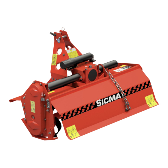
- Page 1 TILLER TILLER /085•105•125 USER AND MAINTENANCE MANUAL Light mobile tiller TRANSLATED INSTRUCTIONS 903870002~01 12/2020...
-
Page 3: Table Of Contents
CONTENTS INTRODUCTION SOME NOTES REGARDING THE USER MANUAL DECLARATION OF CONFORMITY DELIVERY LETTER TILLER IDENTIFICATION AND MANUAL CODE GENERAL DELIVERY NOTES TILLER COMPOSITION SAFETY LIST OF RESIDUAL RISKS SAFETY PRESCRIPTIONS DEFINITIONS CONVENTIONAL SYMBOLS OPERATOR REQUIREMENTS CLOTHING AND PPE SAFE USE OF THE MACHINE INTENDED USE SAFETY DEVICES 2.10... - Page 4 QUICK CONSULTATION TABLES 14.1 TABLE OF TIGHTENING TORQUES 14.2 TROUBLESHOOTING 14.3 LUBRICATION INTERVALS SPARE PARTS WARRANTY NOTES SA Tiller - 4 -...
-
Page 5: Introduction
Thank you for purchasing an SA Tiller The SA Tiller is manufactured by SICMA S.p.A, which has been manufacturing agricultural machines for over 40 years. The SA Tiller has all safety and quality requisites required for this type of equipment. -
Page 6: Declaration Of Conformity
The machine is delivered accompanied by the following Declaration of Conformity. EC DECLARATION OF CONFORMITY The company Sicma s.p.a. - C.da Cerreto, 39 - 66010 Miglianico (Ch) - Italy Tel.: +39 0871 95841 - Fax: +39 0871 950295 e-mail: info@sicma.it - http://www.sicma.it... -
Page 7: Delivery Letter
The identification code of this manual is indicated on the cover. Take note of the number so that, in the event that this manual is lost or damaged, a copy may be requested from SICMA or from your nearest dealer, quoting the serial number indicated on the CE plate. Light mobile tiller... -
Page 8: General Delivery Notes
Spare parts or ancillary equipment are sometimes placed in separate containers. TILLER TILLER In the event of damage or missing parts immediately inform SICMA or its local /085•105•125 USER AND MAINTENANCE MANUAL representatives, the carrier or its insurance agent, providing details and/or photos. -
Page 9: Tiller Composition
TILLER COMPOSITION Ref. Description Frame Lower 3-point hitch Upper 3-point hitch Telescopic drive shaft guard 3-point hitch mast Rotor Hoes Side skids Drive sump Bonnet Drive shaft hook SA Tiller - 9 -... -
Page 10: Safety
SAFETY LIST OF RESIDUAL RISKS Even though SICMA has done everything possible to ensure that the equipment meets the current safety standards as laid down in 2006/42/CE Directive, some residual risks, although reduced, still persist: • CUTTING HAZARD DUE TO CONTACT WITH TOOLS (rotor);... -
Page 11: Conventional Symbols
CRITICAL AREA: The critical area is that between the tractor and the equipment (PTO drive shaft area). ZERO ENERGY STATE: The "Zero Energy State" is defined as the state in which the Tiller is to be set before performing any cleaning, lubrication and maintenance operation. The operator must carry out the following to set the Tiller to the "Zero Energy State": •... -
Page 12: Clothing And Ppe
WARNING! It is absolutely forbidden to tamper with the equipment for any reason. Any arbitrary modification made to this machine exempts SICMA from any responsibility for damages or injuries caused to operators, third parties and property and will result in invalidation of the warranty. -
Page 13: Safety Devices
Ensure therefore that the safety pictograms are in good condition and, if they are damaged, replace them with other original ones by relocating them in their place of origin. Make a request to SICMA or your nearest dealer quoting the reference codes shown on the following pages. SA Tiller... - Page 14 LOCATION OF SAFETY PICTOGRAMS SA Tiller - 14 -...
- Page 15 MEANING OF SAFETY PICTOGRAMS REF. STICKER DESCRIPTION CODE CAUTION Read all instructions and safety rules carefully before using the 4781029 machine. Switch off the engine Qt. 1 and remove the key before carrying out maintenance or repairs. 1000 1000 ROTATING PARTS Danger of injury to the feet, keep a safe 4781011 distance from the machine Qt.
-
Page 16: Unloading And Unpacking The Tiller
RISK OF IMPACT 4781005 Pay attention when moving the Qt. 1 machine body. 4781320 Oil filling point Qt. 2 UNLOADING AND UNPACKING THE TILLER CRUSHING HAZARD! Qualified staff that have read and understood the safety prescriptions must unload the Tiller from the lorry and handle the Equipment in the work place. These manoeuvres should be supervised by an experienced manager. In all cases, ... -
Page 17: Tiller Packaged In Wooden Box
CUTTING HAZARD! In the event that the Tiller arrives wrapped in a protective film, remove it with the aid of a cutter wearing anti-cut gloves; take care not to injure yourself and not damage the Tiller itself. CONTAMINATION HAZARD! Do not dispose of the packaging in the environment, but contact specialist collection agencies. Check the transport document or packing list supplied and, if necessary, act as described in section 1.5 "General notes on delivery". -
Page 18: Technical Specifications
TECHNICAL SPECIFICATIONS The table below outlines the technical specifications of the SA Tiller. Machine type SA/0 85 SA/105 SA/125 Overall width (A) 1145 1345 Working width (B) 1050 1250 Displacement (E) Height (C) Tiller Side clearance (D) Work depth WEIGHT (standard) Number of rotor revolutions Revs/min Rotor pipe diameter Rotor pipe thickness Rotor Rotor work diameter 4 hoes/... -
Page 19: Start-Up
START-UP INJURY HAZARD! Only qualified operators who have read and understood the safety instructions can perform the operations described below. Moreover, they must check that there are no persons, animals and properly exposed in the area where the connection is made to the tractor. The operator and any assistants must have PPE (Personal Protective Equipment) available and use it as required. -
Page 20: Pto Drive Shaft Coupling
PTO DRIVE SHAFT COUPLING Before installing the PTO drive shaft, the operator must: • Read and understand the manual of the PTO drive shaft and of the tractor; • Check that the number of revs. and the direction of rotation of the tractor PTO correspond to those of the Tiller. -
Page 21: Check The Stability Of The Tractor-Tiller Complex
CHECK THE STABILITY OF THE TRACTOR-TILLER COMPLEX Tiller weight changes the stability of the tractor-Tiller complex, influencing steering and braking capability. Therefore proceed at a moderate speed. In particular, it should be noted that the front axle must always be carrying a load of at least 20% of the weight of the tractor-Tiller unit. Check the lifting capacity and stability of the tractor using the following formula and, if necessary, before applying the front weights. -
Page 22: Adjustments
Tiller or the PTO drive shaft. WARNING! SICMA shall not be liable for damage deriving from incorrect modification of the clutch calibration. However, adjustment becomes necessary if the clutch is triggered too frequently, while operating on easily machinable soils, i.e. neither hard nor compact: this means that the clutch calibration is too low. -
Page 23: Adjusting The Lateral Displacement Of The Mast
SA Tillers are supplied as standard with a manually movable 3-point frame that allows translation of the frame on the right side of the tractor (according to the direction of travel) of a maximum “X” of 240mm for the SA/085, 340mm for the SA/105 and 440mm for the SA/125. This option allows easier processing of the ground in special circumstances assessed on a case-by-case basis by the operator. -
Page 24: Use
The Tiller is interchangeable equipment (Machinery Directive art. 1 paragraph b) and to work it must be connected to a tractor; it is from the tractor itself that all its controls are managed. The operator must refer to the tractor user’s manual in order to ensure proper functioning of the Tiller. -
Page 25: Stops
Once the work has been completed, the operator must: • Engage the parking brake; • Turn off the engine, remove the start key and keep it; • Disconnect the drive shaft from the tractor PTO and position it on the dedicated hook; • Restart the tractor and, ensuring that there are no exposed persons or animals, move to the storage place. -
Page 26: Cleaning
EMERGENCY STOP The emergency stop procedure should be carried out in the event of a hazard or malfunction and consists of: • Turn off the PTO to stop the Tiller and stop the tractor; • Engage the parking brake; • Turn off the engine, remove the start key and keep it; • Identify the cause of the emergency stop and, if necessary, consult the “Troubleshooting”... -
Page 27: Check And Replacement Of Oil In The Transmission Assembly
Failure to comply with maintenance standards and schedule compromises the proper operation of the machine and its service life, and voids the warranty. For all other maintenance, see sec. 14.2 (“Troubleshooting”) or contact the Manufacturer or its After-sales centres. Given the complexity of the equipment, repairs, modifications, non-routine maintenance other than those listed below must NOT take place without consulting the Manufacturer or their support centre. -
Page 28: Control And Replacement Of The Oil In The Lateral Drive Sump
• Top up with AGIP-ENI BLASIA 150 type oil until the level is restored as indicated above; • Refit and tighten the filler cap “A”; OIL REPLACEMENT (The first time after the first 50 hours and then every 500 hours) To replace the oil, proceed as follows: • Unscrew the filler cap/vent “A”; • Aspirate the spent oil through the hole of the cap “A”; •... -
Page 29: Greasing
The use of non-original spare parts exempts SICMA from any responsibility for damage or injuries to operators, third parties and property and causes immediate forfeiture of the warranty. -
Page 30: Pto Drive Shaft
REPLACING ALL HOES (When hoe blades are worn out) To replace all hoe blades, proceed as follows: • Prop up the Tiller as described above; • Replace one hoe at a time on one of the two end flanges as described in the previous section, replacing all parts (screws, hoe, washers and nuts) in their original positions. •... -
Page 31: Quick Consultation Tables
QUICK CONSULTATION TABLES The following pages, state the conditions and hypothesis of intervention for each TIGHTENING TORQUES of the cases stated above, in table form. bolt class 14.1 TABLE OF TIGHTENING TORQUES 10.9 Threading Lb-ft Lb-ft Check the condition and the efficiency of all screws and bolts every day. If necessary, replace them immediately by requesting them from the manufacturer. -
Page 32: Lubrication Intervals
14.3 LUBRICATION INTERVALS RECOMMENDED LUBRICANTS AGIP-ENI BLASIA 150 GREASE AGIP GREASE MU EP 2 Ref. INTERVAL IN HOURS DESCRIPTION OF THE INTERVENTION AFTER THE FIRST 50 • Replacing the bevel transmission assembly oil WORKING HOURS • Replacing the lateral casing oil EVERY 8 WORKING HOURS •... -
Page 33: Spare Parts
Repairs and replacements of damaged or worn parts must be carried out using original parts, which must be requested from the Dealer or purchased via the website https://SICMA.it/. Please note that a request for spare parts must be accompanied by the following information: •... -
Page 34: Notes
NOTES _______________________________________________________________ _______________________________________________________________ _______________________________________________________________ _______________________________________________________________ _______________________________________________________________ _______________________________________________________________ _______________________________________________________________ _______________________________________________________________ _______________________________________________________________ _______________________________________________________________ _______________________________________________________________ _______________________________________________________________ _______________________________________________________________ _______________________________________________________________ _______________________________________________________________ _______________________________________________________________ _______________________________________________________________ _______________________________________________________________ _______________________________________________________________ _______________________________________________________________ _______________________________________________________________ _______________________________________________________________ _______________________________________________________________ _______________________________________________________________ _______________________________________________________________ _______________________________________________________________ SA Tiller - 34 -... - Page 36 SICMA S.p.A. Contrada Cerreto, 39 66010 MIGLIANICO (CH) - ITALY Tel. +39 087195841 - fax +39 0871950295 www.sicma.it...
Need help?
Do you have a question about the SA/085 and is the answer not in the manual?
Questions and answers