Table of Contents
Advertisement
Quick Links
NATURAL DRAFT DIESEL HEATER
INSTALLATION & OPERATING
INSTRUCTIONS
90
Over
Years In
Production!
These installation and operating instructions
apply the following Dickinson models:
Newport
Lofoten
Dickinson Marine #101 - 17728 66 Ave,
Surrey, BC, Canada, V3S 7X1
Email: info@dickinsonmarine.com
Caution! Failure to adhere to the safety warnings listed in this manual could result in
Please familiarize yourself with the contents of this manual before installing and operating the appliance
INSTALLER: Leave this manual with the appliance.
Alaska
Antarctic
damage to property or severe personal injury!
Serial #: _ _ _ _ _ _ _ _ _ _ _ _ _ _ _ _ _ _ _ _ _
For Marine Use Only
CONSUMER: Retain this manual for future reference.
Advertisement
Table of Contents

Related Manuals for Dickinson 00-NEW


Summary of Contents for Dickinson 00-NEW
- Page 1 Alaska Newport Lofoten Antarctic Dickinson Marine #101 - 17728 66 Ave, Surrey, BC, Canada, V3S 7X1 Email: info@dickinsonmarine.com Caution! Failure to adhere to the safety warnings listed in this manual could result in damage to property or severe personal injury!
-
Page 2: Service Notes
All dimensions, measurements and weights are approximate. dickinsonmarine.com info@dickinsonmarine.com @dickinsonmarine @dickinsonmarine1932 /dickinsonmarine We’d love to see your Dickinson Marine pictures & videos, please follow, tag us and share! Service notes: Appliance model: Fuel Type: Serial No.: Date of purchase:... -
Page 3: Table Of Contents
………………………………………………………………Hot Water Coils 1. INTRODUCTION Since 1932, Dickinson Marine have been among the most well known producers of marine appliances on the market. The uncompromising quality and legendary robustness of Dickinson appliances have earned them a place in the hearts of sailors and fishing crews for decades. -
Page 4: General Appliance Warnings
DO NOT operate while under the influence of drugs or alcohol Do not use any other fuel metering device other than those manufactured by Dickinson Marine. Parts of the appliance become very hot when in use. To avoid burns DO NOT touch any surfaces which may be hot. -
Page 5: Warranty
DICKINSON WARRANTY POLICY Dickinson Marine appliances are covered under limited warranty for a period of one year dated from the purchase of the product by the end user with proof of purchase or a registered warranty. The warranty card at the bottom of this page should be copied for your records and returned to Dickinson to activate your warranty within 90 days of your purchase. -
Page 6: Conditions & Limitations
This warranty is limited to claims submitted in writing within a one-year period following the date of purchase. If any part of your new product fails because of a manufacturing defect within the warranty period Dickinson offers to replace said parts free of charge, provided, however, that such parts have not been improperly repaired, altered or tampered with or subjected to misuse, abuse or exposed to corrosive conditions. -
Page 7: About This Appliance
Diesel Metering Valve See page 43 for diesel valve maintenance Signature Dickinson styling & construction See page 7 to see how Dickinson appliances have FIG 1 evolved over the decades. Draft assist fan controls Drip tray See pages 36-37 for... - Page 8 An evolution of the earlier Polar model and precursor to the Dickinson Antarctic, the Arctic A later 1975 Dickinson Alaska (below) where we see a was fitted with a cast iron top departure from the coloured enamel finishes of the 50’s &...
- Page 9 In British Columbia it remains pretty common to board a How important is the chimney? fishing vessel and find a Dickinson stove that’s been serving up meals for over 40-50 years. While oil ranges have become largely obsolete outside of an offshore environment, there is...
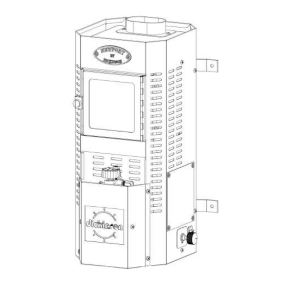
- Page 10 DIMENSIONS & MODELS NEWPORT 00-NEW overall W: 8.50” H: 19.75” D: 10.50” ⌀ : Flue 3” ⌀ Burner 6” Max BTU: 16,250 Valve cal.: Coil options: 1 turn Fan control: Built-in FIG 2 ALASKA 00-ALA overall W: 13.00” H: 23.00”...
-
Page 11: Safety Clearances
SAFETY CLEARANCES TWO INCH MIN. CLEARANCE TO PROTECTED SURFACE (EXCEPT WALL MOUNTED MODEL) VIEW FROM TOP 12 INCHES 12 INCHES FIG 6 18 INCH MIN. CLEARANCE TO NEAREST SURFACE Bulkhead Insulation board Ceramic tile FIG 7 Bulkhead Insulation board Half Inch Air gap FIG 9 Steel... -
Page 12: Ratings & Specifications
RATINGS & SPECIFICATIONS Part no’s. 00-NEW, 00-ALA, 00-LOF, 00-ANT Model’s Newport, Alaska, Lofoten, Antarctic Product type Natural Draft Marine Diesel Heater Conforms to THE APPLIANCE PART NO. INCLUDES standard electrical input rating 12 Vdc, 0.4 Amp 1x Natural Draft Diesel Appliance... -
Page 13: Natural Draft
NATURAL DRAFT What is Natural Draft? CHIMNEY A natural draft appliance relies on the natural chain reaction kick started TERMINATION by lighting an oil fire inside the burner. Creating heat in the burner leaves it nowhere to go but up, heating up the appliance body and the Draft created naturally chimney. -
Page 14: Internal Burner Components
INTERNAL BURNER COMPONENTS 6-inch Burner Components COMPATIBLE WITH ALL DICKINSON HEATER MODELS FIG 11 A. Low Sulfur Baffle (LSB) #03-090 The purpose of the low sulfur baffle is to reflect rising heat back onto the superheater keeping it hotter than it would otherwise remain. - Page 15 OIL METERING VALVE Valve flow The importance of the oil level settings A natural draft diesel appliance relies on an uninterrupted flow of fuel to keep burning and not extinguish. Setting indicator (This valve is shown set The amount of fuel it receives is carefully pre determined by the settings and to the ‘OFF’...
-
Page 16: Installation Warnings
Installing a natural draft diesel appliance without adhering to the warnings, requirements and stipulations in this manual can result in damage to property, injury and even death. Please be aware that Dickinson bear no responsibility for unsatisfactory performance, damage, loss or personal injury resulting from non-conforming product installations that do not meet the requirements in this manual. -
Page 17: Heating Capacity
Failure to meet one or more of these install requirements may result in unsatisfactory or unreliable operation of the appliance. Please note that Dickinson bear no responsibility for unsatisfactory performance damage or loss resulting from non- conforming product installations that do not meet the requirements in this manual. -
Page 18: Items Specific To Sailboats
ITEMS SPECIFIC TO SAILBOATS Facing direction? The appliance should ideally face the bow or An appliance with a An appliance with a standard front mounted valve stern, especially on a sailboat. Fuel is standard front mounted gravity fed from the metering valve to the facing port or starboard may struggle to supply valve facing bow or stern burner so if the valve drops below the level... -
Page 19: Choosing An Optimal Install Location
Children & pets See page 24 All surfaces of a Natural draft Dickinson Diesel Safety clearances appliances become hot while in operation. Utmost care must be taken to make sure vulnerable... -
Page 20: Install Checklist
(see page 22, fig 28) 3. Check the Safety Clearances around the appliance. 11. Assemble the chimney Each appliance has its required safety clearances. Dickinson Natural Draft chimney pipe is easy to assemble and doesn’t require the use of clamps or Review these verify... - Page 21 CHIMNEY VARIATIONS ONLY USE OEM DICKINSON MARINE CHIMNEY COMPONENTS TO VENT A DICKINSON APPLIANCE 8’ 7’ 6’ 5’ 4’ 3’ 2’ The ideal height for the barometric damper is between the 2-3 foot mark above the appliance 1’ FIG 20...
-
Page 22: Unsupported Chimney Configurations
FIG 22 Other appliances and models It may not be possible to replace a previous model Dickinson appliance or other appliance with this one in the same configuration. This appliance may not support the chimney types, configurations and systems used on other appliances including other Dickinson appliances. -
Page 23: Planning The Install
PLANNING THE INSTALL 8’ 7’ Level foundation When choosing a surface on which to install the appliance, ensure that It does not sit at an angle or pitched forward or back (fig 23, below) 6’ In an appliance that is not level, fuel will pool to one side of the burner and result in partial combustion and carbon rich flames. - Page 24 A light and effective stainless steel replacement for a traditional charlie noble, the Dickinson deck fittings are extruded by hand using a process called spinning. Each one is then finely electro-polished as an added measure...
- Page 25 Installs at angles (E) exceeding 15º, vertical installs (F) and installs that do not conform to the instructions in this manual are not supported. Please note that Dickinson bear no responsibility for unsatisfactory performance damage or loss resulting from non-conforming product installations that do not meet the requirements in this manual.
-
Page 26: Flue Collar Connection
FLUE COLLAR CONNECTION Dickinson Chimney pipes Attaching chimney Dickinson chimney pipes are laser cut, rolled and crimped from high quality 304 stainless pipe to flue collar steel. Each one fits snuggly into a second pipe, the deck fitting, cap or elbow eliminating The chimney pipe must be the need for tape or additional sealant. -
Page 27: Fuel Metering
FUEL METERING The SEAT The seat which the valve needle sits in is the narrowest THE VALVE: CAUTION! point of flow for fuel inside the valve. This makes it a possible bottle neck that must not be allowed to become plugged by debris or deposits from contaminated fuel. - Page 28 FUEL METERING Cont’d Turn Counter VALVE OPERATION: clockwise to ‘ON’ to open fuel flow open Fuel shut Fuel shut OIL LEVEL off closed off open Lowered FIG 40 FIG 41 FIG 38 FIG 39 ↑ PRIMED ↑ FILLING ↑ EMPTY ↑...
-
Page 29: Fuel Supply System
If your appliance is being supplied from a main fuel tank, the Only use number 2 diesel in a Dickinson appliance. If you have overflow line must return to the main tank. an appliance with a special metering valve rated for number 1... - Page 30 When When installing a Walbro fuel pump supplied by Dickinson, the best results not in use, relying on the valve alone to shut off fuel flow may cause wear to will be obtained by locating the pump somewhere it will ‘pull’...
-
Page 31: Pump Installation
PUMP INSTALLATION Orientation The pump is best installed oriented with its outlet pointing Wiring upwards. If installing the pump upright is not possible, the pump can be installed on its side. Please note that a pump We recommend wiring the pump into a 12v control circuit installed on its side may suffer from increased wear over time with a 5 amp fuse so that power to the pump can be and can result in limited pressure. -
Page 32: Draft Assist Fan Wiring
DRAFT ASSIST FAN WIRING This appliance is equipped with a 12v draft assist fan. While running the fan is not required in order to light and operate the appliance, it is strongly recommended as it will offer you a greater degree of control over the quality of combustion in the burner. When to use the draft assist fan Use the fan during light-up, for higher fuel settings or if conditions are unusually windy. -
Page 33: Hot Water Coils
HOT WATER COILS Dickinson Natural Draft Diesel appliances have the option of adding a water coil to supply hot water. Appliances can be purchased with a water coil already installed, or a coil can be retrofitted to an existing appliance. - Page 34 Additionally it is strongly recommended that everyone putting a natural draft appliance into operation familiarizes themselves with the diesel appliance install, maintenance and operating video guides published by Dickinson Marine. These videos are available at dickinsonmarine.com/pages/support can be found on youtube.com/@dickinsonmarine1932...
- Page 35 READ THIS BEFORE LIGHTING UNMAINTAINED APPLIANCE FLOODED OR HOT BURNER RISK Never light a flooded burner – the priming fuel should form a & CHIMNEY RISK pool roughly 3 inches across. Lighting an appliance that has not seen regular maintenance If you see more fuel than this, do not light it! can represent a fire safety hazard.
-
Page 36: Operating Instructions
FOR YOUR SAFETY READ BEFORE LIGHTING WARNING: If you do not follow these instructions exactly, a fire or explosion may result causing property damage, personal injury, or loss of life. • An appliance if the metering valve shows signs of overflow This appliance is equipped with a natural draft breeze burner •... - Page 37 LIGHTING-UP PROCEDURE FUEL SETTINGS ------------------------------------------ FAN SETTINGS 1. Priming the burner Open the shut-off valve at the fuel tank and set the metering valve control 5 - 10 knob to its highest setting (# 5) min. Priming the burner will take between 5-10 minutes. The burner is primed once a pool of fuel roughly 2.5-3 inches in diameter has formed inside it.
- Page 38 LIGHTING-UP PROCEDURE cont’d FUEL SETTINGS ------------------------------------------ FAN SETTINGS 5. Accumulating heat At this stage, even though the appliance has been burning for some time, we’re still building up heat inside the burner. It can take around an hour or more for heat to spread evenly throughout the appliance. Adjusting fuel settings too high before sufficient heat has accumulated in the burner will result in incomplete combustion and soot.
- Page 39 THE IMPORTANCE OF THE FUEL AIR MIXTURE It’s easy to underestimate the importance of air flow when operating a natural draft diesel appliance. In order for a natural draft diesel appliance to operate safely and burn cleanly without soot or smoke, adequate air flow into the cabin is vital.
- Page 40 OPERATING TIPS Always clean new and old metering valves alike before first Some fans have low amperage motors and need to have their use (see page 43 for instructions) Clean the valve at the speed controls turned up to a high setting to initiate spinning beginning of each season, anytime the appliance has sat of the fan blades.
-
Page 41: Barometric Damper Settings
BAROMETRIC DAMPER SETTINGS The burner will require less air when operating at lower fuel settings. Having too much air on low fuel settings may cause the flames to drop down into the burner pot. Reductions in air can be managed by turning off the fan or adjusting the barometric damper. -
Page 42: Maintenance
5. MAINTENANCE SYSTEM MAINTENANCE Understanding how to go about maintaining a natural draft diesel appliance is simplified if you learn to view the installation as a single system – it is best viewed as a single system that converts liquid diesel fuel into heat & exhaust. When we consider the install as a single system, we can see that ensuring flow through the whole system is crucial to its trouble-free operation. -
Page 43: Fuel Filter Maintenance
FUEL FILTER MAINTENANCE FUEL LINE MAINTENANCE FUEL FILTERS FUEL LINE A fuel filter is required for the installation of a natural draft appliance in order Deposits of carbon and dust from the burn chamber will collect to keep naturally occurring diesel fuel contaminants out of the fuel lines and inside the fuel line leading to the burner from the metering the moving parts inside the metering valve. - Page 44 VALVE MAINTENANCE Valve maintenance The job of the metering valve is to maintain a steady oil level within the valve & burner, and to precisely meter out the correct amounts of fuel for each numbered fuel setting. In order to function as intended, the metering valve must be kept clean.
-
Page 45: Fuel Pump Maintenance
FUEL PUMP MAINTENANCE FIG 89 FIG 87 FUEL PUMPS In order to supply the appliance reliably a fuel pump must receive filtered fuel. It is best to orient the fuel pump so that it must draw fuel upwards from a source below. -
Page 46: Troubleshooting
Pictures of the appliance install and the chimney (if applicable) Please bear in mind that Dickinson technicians are available for remote support only and are by no means authorized to attend service calls or offer technical support or help in person. -
Page 47: Appliance Produces Soot
APPLIANCE PRODUCES SOOT APPLIANCE BLOWS OUT CAUTION: ALWAYS FOLLOW THE MANUFACTURER’S LIGHTING INSTRUCTIONS FOR THIS APPLIANCE FOUND ON PAGE 35. FAILURE TO ADHERE TO SAFE RECOMMENDED LIGHTING PROCEDURES CAN RESULT IN INJURY, DAMAGE TO PROPERTY OR EVEN DEATH. Appliance Appliance produces blows out soot... -
Page 48: Not Producing Enough Heat
See a video • Opening barometric off fan air / close demonstration of this and other damper barometric damper to steps on the Dickinson Marine • Turning on fan help flames raise above YouTube channel. See page 38 burner ring. -
Page 49: Valve Overflowing
& seat of the metering valve. See a video demonstration of this and other steps on the Dickinson Marine YouTube channel. Valve overflow fitting... -
Page 50: Flames Burning Inside Burner Pot
FLAMES BURNING INSIDE POT FAN OPERATION IS NOISY CAUTION: ALWAYS FOLLOW THE MANUFACTURER’S LIGHTING INSTRUCTIONS FOR THIS APPLIANCE FOUND ON PAGE 35. FAILURE TO ADHERE TO SAFE RECOMMENDED LIGHTING PROCEDURES CAN RESULT IN INJURY, DAMAGE TO PROPERTY OR EVEN DEATH. Flames won’t rise above the OPERATION... -
Page 51: Glossary Of Terms
Winterized diesel, also called stove oil Puddle of fuel burned inside burner to accumulate heat Primer fuel Diesel, #2 The automotive diesel Dickinson appliances are calibrated for A non-flammable surface Protected surface DP-CAP The round, Dickinson DP style chimney cap... -
Page 52: List Of Illustrations
LIST OF ILLUSTRATIONS PAGE # DESCRIPTION PAGE # DESCRIPTION TITLE NEWPORT HEATER IMAGE FAN SETTING: MED NEWPORT MODEL FUEL SETTING: #5 ALASKA MODEL FAN SETTING: OFF LOFOTEN MODEL LEAN BURN ANTARCTIC MODEL RICH BURN SAFETY CLEARANCES UNBALANCED COMBUSTION EXAMPLE OF TILED SURFACE... - Page 53 All rights reserved. No part of this manual may be reproduced without permission in writing from Dickinson Marine. Dickinson also reserves the right to modify or change without notice, any materials, applications, equipment, accessories, and/or prices. All dimensions, measurements and weights are approximate.
Need help?
Do you have a question about the 00-NEW and is the answer not in the manual?
Questions and answers