Table of Contents
Advertisement
Quick Links
UNVENTED (VENT-FREE)
NATURAL GAS FIREPLACE
This appliance may be installed in an aftermarket* manufactured (mobile) home,
where not prohibited by state or local codes.
* Aftermarket: Completion of sale, not for purpose of resale, from the manufacturer
OWNER'S OPERATION AND INSTALLATION MANUAL
CGF265NVA
AND
CGF280NT
®
WARNING: If the information in this manual is not
followed exactly, a fire or explosion may result caus-
ing property damage, personal injury, or loss of life.
— Do not store or use gasoline or other flammable
vapors and liquids in the vicinity of this or any other
appliance.
— WHAT TO DO IF YOU SMELL GAS
• Do not try to light any appliance.
• Do not touch any electrical switch; do not use
any phone in your building.
• Immediately call your gas supplier from a
neighbor's phone. Follow the gas supplier's in-
structions.
• If you cannot reach your gas supplier, call the
fire department.
— Installation and service must be performed by a
qualified installer, service agency, or the gas supplier.
Save this manual for future reference.
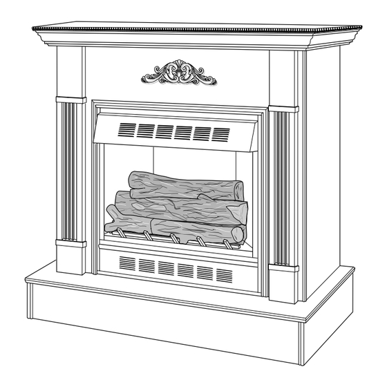
Shown with optional
cabinet mantel and
hearth base.
WARNING: Improper installation,
adjustment, alteration, service,
or maintenance can cause injury
or property damage. Refer to this
manual for correct installation
and operational procedures. For
assistance or additional infor-
mation consult a qualified in-
staller, service agency, or the
gas supplier.
WARNING: This is an unvented
gas-fired heater. It uses air (oxy-
gen) from the room in which it is
installed. Provisions for adequate
combustion and ventilation air
must be provided. Refer to Air for
Combustion and Ventilation sec-
tion in this manual.
Advertisement
Table of Contents

Related Manuals for Desa Comfort Glow CGF265NVA


Summary of Contents for Desa Comfort Glow CGF265NVA
- Page 1 This appliance may be installed in an aftermarket* manufactured (mobile) home, where not prohibited by state or local codes. * Aftermarket: Completion of sale, not for purpose of resale, from the manufacturer OWNER’S OPERATION AND INSTALLATION MANUAL CGF265NVA CGF280NT ® WARNING: If the information in this manual is not followed exactly, a fire or explosion may result caus- ing property damage, personal injury, or loss of life.
-
Page 2: Table Of Contents
CONTENTS SAFETY INFORMATION SECTION Safety Information ... 2 Product Identification ... 4 Local Codes ... 5 Unpacking ... 5 Product Features ... 5 Air for Combustion and Ventilation ... 6 Installing ... 9 Check Gas Type ... 9 Assembling and Attaching Brass Trim ... 10 Installation Clearances ... - Page 3 SAFETY INFORMATION Continued 102664 WARNINGS WARNING ICON G 001 WARNING: Any change to this fireplace or its controls can be dangerous. 1. This appliance is only for use with the type of gas indicated on the rating plate. This appliance is not convertible for use with other gases. 2.
-
Page 4: Product Identification
PRODUCT IDENTIFICATION Top Louvered Front Log (#1) Front Burner Left Front Branch (#4) Base Right Front Branch (#5) Figure 1 - Log Base Assembly Hood Firebox Support Screen Assembly Figure 2 - Fireplace Rear Log (#2) Rear Burner Regulator Top Outer Casing Bottom Louver Assembly... -
Page 5: Local Codes
This results in increased heating comfort. This can also result in lower gas bills. Variable Manual Control (CGF265NVA) These fireplaces have a variable manual control valve which allows the user to choose the heat setting that best suits his needs. Any setting between low and high... -
Page 6: Providing Adequate Ventilation
AIR FOR COMBUSTION VENTILATION Today’s homes are built more energy efficient than ever. New materials, increased insulation, and new construction methods help reduce heat loss in homes. Home owners weather strip and caulk around windows and doors to keep the cold air out and the warm air in. - Page 7 AIR FOR COMBUSTION VENTILATION Continued 102664 DETERMINING AIR FLOW FOR FIREPLACE LOCATION Determining if You Have a Confined or Unconfined Space Use this work sheet to determine if you have a confined or unconfined space. Space: Includes the room in which you will install fireplace plus any adjoining rooms with doorless passageways or ventilation grills between the rooms.
-
Page 8: Ventilation Air
AIR FOR COMBUSTION VENTILATION Continued WARNING ICON G 001 If the area in which the heater may be operated is smaller than that defined as an unconfined space, provide adequate combus- tion and ventilation air by one of the methods described in the National Fuel Gas Code, ANSI Z223.1, 1992, Section 5.3. -
Page 9: Installing
INSTALLING 102664 NOTICE A qualified service person must install fireplace. Follow all local codes. WARNING ICON G 001 Never install the fireplace • in a bedroom or bathroom • in a recreational vehicle • where curtains, furniture, clothing, or other flammable objects are less than 36 inches from the front, top, or sides of the fireplace •... -
Page 10: Assembling And Attaching Brass Trim
INSTALLING Continued ASSEMBLING AND ATTACHING BRASS TRIM Note: The instructions below show assembling and attaching brass trim to fireplace. Do not yet install trim if performing a built-in installation (see page 14, Built- In Fireplace Installation) 1. Remove packaging from three pieces of brass trim. 2. -
Page 11: Installation Clearances
INSTALLING Continued 102664 INSTALLATION CLEARANCES WARNING ICON G 001 Maintain the minimum clearances. If you can, provide greater clearances from floor, ceiling, and adjoining wall. Carefully follow the instructions below. This will ensure safe installation. Minimum Wall and Ceiling Clearances (see Figure 7) A. - Page 12 INSTALLING Continued 2. Break off nailing flanges (see Figure 8) with hammer or pliers. 3. Place mantel and base in desired location. Place heater in front opening of mantel. Make sure all pieces fit properly. Remove mantel. 4. Mark floor and base or wall for gas line entrance. Make sure there is enough clearance between heater and mantel for gas line.
- Page 13 102664 Figure 10 - Installing Cabinet Mantel 7. Carefully place fireplace on top of hearth base (Figure 11). Be careful not to scratch or damage hearth base. floor. Open lower louver. Locate screw holes in bottom of base. Secure with wood screws through these holes and into hearth or floor.
-
Page 14: Built-In Fireplace Installation
INSTALLING Continued BUILT-IN FIREPLACE INSTALLATION Built-in installation of this fireplace involves installing fireplace into a framed-in enclosure. This makes the front of fireplace flush with wall. If installing a mantel above the fireplace, but you must follow the clearances shown in Figure 15, page 15. Follow the instructions below to install the fireplace in this manner. - Page 15 INSTALLING Continued 102664 Nails or Wood Screws Nailing Flanges Figure 14 - Attaching Fireplace to Wall Studs Mantel Clearances for Built-In Installation If placing mantel above built-in fireplace, you must meet minimum clearance between mantel shelf and top of fireplace opening. 10"...
-
Page 16: Installing Gas Piping To Fireplace Location
INSTALLING Continued INSTALLING GAS PIPING TO FIREPLACE LOCATION A qualified service person must connect fireplace to gas supply. Follow all local codes. Installation Items Needed Before installing fireplace, make sure you have the items listed below. • piping (check local codes) •... -
Page 17: Connecting Fireplace To Gas Supply
INSTALLING Continued 102664 Approved Flexible Gas Line 3" Minimum Figure 16 - Gas Connection * Purchase the optional A.G.A. design-certified manual shutoff valve from your dealer. See Accessories, page 38. CONNECTING FIREPLACE TO GAS SUPPLY Installation Items Needed • 5/16" hex socket wrench or nut-driver •... -
Page 18: Checking Gas Connections
INSTALLING Continued 4. Route flexible gas line from manual shutoff valve into fireplace through side or rear access panel. Route flexible gas supply line through fireplace access door. Most building codes do not permit concealed gas connections. A flexible gas line is provided to allow accessibility from the fire- place. - Page 19 INSTALLING Continued 102664 Test Pressures Equal To or Less Than 1/2 PSIG 1. Close manual shutoff valve (see Figure 19). 2. Pressurize supply piping system by either using compressed air or opening main gas valve located on or near gas meter. 3.
-
Page 20: Installing Logs
INSTALLING Continued INSTALLING LOGS Failure to position the parts in accordance with these diagrams or failure to use only parts specifically approved with this heater may result in property damage or personal injury. Each log is marked with a number. These numbers will help you identify the log when installing. -
Page 21: Operating Fireplace (Thermostat-Controlled Model)
INSTALLING Continued OPERATING FIREPLACE Thermostat- Controlled Model CGF280NT 102664 WARNING ICON G 001 You must operate this fireplace with the fireplace screen in place. Make sure fireplace screen is in place before running fireplace. 5. Install fireplace screen by slipping notches of fireplace screen over screws on front of fireplace (see Figure 24). -
Page 22: Lighting Instructions
OPERATING FIREPLACE Thermostat- Controlled Model Continued LIGHTING INSTRUCTIONS WARNING ICON G 001 You must operate this fireplace with the fireplace screen in place. Make sure fireplace screen is installed before running fireplace. During initial operation of new fireplace, burning logs will give off a paper-burning smell. -
Page 23: To Turn Off Gas To Appliance
Continued OPERATING FIREPLACE Manually-Controlled Model CGF265NVA 102664 8. Turn control knob counterclockwise burners should light. Set control knob to any heat level between HI and LO. Do not try to adjust heating levels by using the manual shutoff valve. TO TURN OFF GAS TO APPLIANCE... -
Page 24: Lighting Instructions
OPERATING FIREPLACE Manually-Controlled Model Continued LIGHTING INSTRUCTIONS WARNING ICON G 001 You must operate this fireplace with the fireplace screen in place. Make sure fireplace screen is installed before running fireplace. During initial operation of new fireplace, burning logs will give off a paper-burning smell. - Page 25 OPERATING FIREPLACE Manually-Controlled Model Continued 102664 VARIABLE CONTROL OPERATION The variable control valve can be set to any heat setting and flame height desired, by simply turning the control knob until that setting is attained. Even the lowest setting provides realistic flames and glowing embers from two burners. Selecting higher settings produces greater heat output.
-
Page 26: Inspecting Burners
INSPECTING BURNERS Check pilot flame pattern and burner flame patterns often. PILOT FLAME PATTERN Figure 29 shows a correct pilot flame pattern. Figure 30 shows an incorrect pilot flame pattern. The incorrect pilot flame is not touching the thermocouple. This will cause the thermocouple to cool. -
Page 27: Cleaning And Maintenance
CLEANING MAINTENANCE TROUBLE- SHOOTING Note: All troubleshooting items are listed in order of operation. 102664 WARNING ICON G 001 Turn off fireplace and let cool before cleaning. WARNING ICON G 001 You must keep control areas, burners, and circulating air pas- sageways of fireplace clean. - Page 28 TROUBLE- SHOOTING Continued OBSERVED POSSIBLE PROBLEM CAUSE When ignitor button 1. Gas supply turned off or is pressed, there is manual shutoff valve spark at ODS/pilot closed but no ignition 2. Control knob not in PILOT position 3. Control knob not pressed in while in PILOT position 4.
- Page 29 TROUBLE- SHOOTING Continued 102664 OBSERVED POSSIBLE PROBLEM CAUSE One or both burners do 1. Burner orifice(s) not light after ODS/ clogged pilot is lit 2. Burner orifice(s) diameter is too small 3. Inlet gas pressure is too low 4. Mislocated crossover tube Delayed ignition of 1.
- Page 30 TROUBLE- SHOOTING Continued WARNING ICON G 001 If you smell gas • Shut off gas supply. • Do not try to light any appliance. • Do not touch any electrical switch; do not use any phone in your building. • Immediately call your gas supplier from a neighbor’s phone. Follow the gas supplier’s instructions.
-
Page 31: Service Hints
SERVICE HINTS SPECIFICATIONS TECHNICAL SERVICE PARTS CENTRALS 102664 When gas pressure is too low • pilot will not stay lit • burners will have delayed ignition • fireplace will not produce specified heat • propane/LP gas supply may be low When gas quality is bad •... -
Page 32: Illustrated Parts Breakdown
ILLUSTRATED PARTS BREAKDOWN Log Base Assembly Variable Manually- Controlled Models CGF265NVA 7-1 7-2 102664... - Page 33 101416-14 101976-02 102664 This list contains replaceable parts used in your fireplace. When ordering parts, follow the instructions listed under Replacement Parts on page 38 of this manual. CGF265NVA DESCRIPTION Front Log (#1) Rear Log (#2) Control Valve Left Front Branch (#4)
- Page 34 ILLUSTRATED PARTS BREAKDOWN Log Base Assembly Thermostat- Controlled Models CFG280NT 7-1 7-2 102664...
- Page 35 PARTS LIST Log Base Assembly Thermostat- Controlled Models 102664 This list contains replaceable parts used in your fireplace. When ordering parts, follow the instructions listed under Replacement Parts on page 38 of this manual. CGF280NT PART NUMBER DESCRIPTION 102230-02 Front Log (#1) 102231-02 Rear Log (#2) 11084-38...
- Page 36 ILLUSTRATED PARTS BREAKDOWN Fireplace CGF265NVA CGF280NT 102664...
- Page 37 PARTS LIST Fireplace 102664 This list contains replaceable parts used in your fireplace. When ordering parts, follow the instructions listed under Replacement Parts on page 38 of this manual. CGF280NT CGF265NVA PART NUMBER DESCRIPTION 101357-01 Top Outer Casing 101373-01 Outer Casing...
-
Page 38: Replacement Parts
REPLACEMENT PARTS ACCESSORIES Note: Use only original replacement parts. This will protect your warranty cover- age for parts replaced under warranty. Parts Under Warranty Contact authorized dealers of this product. If they can’t supply original replace- ment part(s), call DESA International’s Technical Service Department at 1-800-DESA LOG (1-800-337-2564). - Page 39 _________________________________________________________________ NOTES _________________________________________________________________ _________________________________________________________________ _________________________________________________________________ _________________________________________________________________ _________________________________________________________________ _________________________________________________________________ _________________________________________________________________ _________________________________________________________________ _________________________________________________________________ _________________________________________________________________ _________________________________________________________________ _________________________________________________________________ _________________________________________________________________ _________________________________________________________________ _________________________________________________________________ _________________________________________________________________ _________________________________________________________________ _________________________________________________________________ _________________________________________________________________ _________________________________________________________________ _________________________________________________________________ _________________________________________________________________ _________________________________________________________________ _________________________________________________________________ _________________________________________________________________ _________________________________________________________________ _________________________________________________________________ _________________________________________________________________ _________________________________________________________________ _________________________________________________________________ _________________________________________________________________ _________________________________________________________________ _________________________________________________________________ _________________________________________________________________ _________________________________________________________________ _________________________________________________________________ _________________________________________________________________ _________________________________________________________________ 102664...
-
Page 40: Warranty Information
WARRANTY INFORMATION Model Serial No. Date Purchased Always specify model and serial numbers when communicating with the factory. We reserve the right to amend these specifications at any time without notice. The only warranty applicable is our standard written warranty. We make no other warranty, expressed or implied. COMFORT GLOW VENT-FREE NATURAL GAS FIREPLACE DESA International warrants this product to be free from defects in materials and components for one (1) year from the date of first purchase, provided that the product has been properly installed, operated and maintained in accordance with...
Need help?
Do you have a question about the Comfort Glow CGF265NVA and is the answer not in the manual?
Questions and answers