Advertisement
harman/kardon
harman/kardon
HS 2X0/230
(HS 210 system and HS 280 system)
2 x 65W 2.1 RECEIVER / HOME CINEMA SYSTEMS
2
ACESSORIES
3
FRONT AND REAR PANELS
TROUBLESHOOTING GUIDE
BASIC SPECIFICATIONS
EXPLODED VIEW AND PARTS
PACKAGE LISTS AND PARTS
NOTE: The HS 210 and HS 280 systems DVD/amplifier units are identical, named "HS 2X0"
on the rear panel, but featuring NO NAME-STICKER on the front panel.
The only difference is the loudspeakers included in the system box.
HS 210 comes with a HKTS 30 system in 2.1 configuration
HS 280 comes with a HKTS 60 system in 2.1 configuration.
Please refer to the HKTS 20+30+60 service manual for information on the speakers.
Released EU2010
CONTENTS
8
10
11
12
Harman
8500 Balboa Boulevard
Northridge, California 91329
Service Manual
ELECTRICAL PARTS LIST
SEMICONDUCTOR PINOUTS
4
PCB DRAWINGS
9
SCHEMATIC DIAGRAMS
Consumer Group, Inc.
HS 2X0/230 Service Manual
13
19
42
52
53
54
56-73
Rev 2, 01/2011
Page 1 of 73
Advertisement

Related Manuals for Harman Kardon HS-210-230


Summarization of Contents
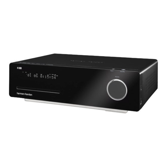
Introduction
HS 2X0S0/230 Two-Channel DVD Receiver
Details the audio, video, and digital connectivity options of the receiver unit.
Supplied Accessories
Supplied Accessories (for HS 280)
Lists and illustrates accessories included with the HS 280 system.
Supplied Accessories (for HS 210)
Lists and illustrates accessories included with the HS 210 system.
Receiver Front-Panel Controls
Front Panel Controls Overview
Details the functions of buttons, display, volume control, and ports on the front panel.
Receiver Information Display
Information Display Indicators
Explains indicators for source, disc type, playback modes, and video status.
Receiver Rear-Panel Connections
Rear Panel Connection Types
Details connectors for power, speakers, digital audio, video, Ethernet, USB, and HDMI.
Subwoofer Controls and Connections
Subwoofer Operation and Setup
Covers level control, phase, power modes, and various input connections.
Remote Control Functions
Remote Control Button Functions
Explains the operation of system power, source selection, playback, and menu navigation buttons.
Troubleshooting
Common System Issues and Solutions
Addresses power, video, audio, subwoofer, disc playback, noise, and remote control problems.
Specifications
HS 2X0S0/230 Receiver Specifications
Details specs for audio, FM tuner, DVD player, and video sections of the receiver.
Speaker System Specifications
Specifies technical details for the SAT TS60 and SAT-TS11 satellite speakers.
HKTS200SUB Subwoofer Specifications
Provides technical specifications for the HKTS200SUB subwoofer.
HS2X0 Component List for Front Panel Board (6742C)
HS2X0 Component List for Volume Button Board (6743C)
Lists components for the volume button board (6743C).
FLI2310 LF Digital Video Converter Data Sheet
FLI2310 Pin Diagram
Shows the pin assignment diagram for the FLI2310 chip.
AM5888S Motor Driver ICs Pin Description
AM5888S Pin Function Details
Lists pin names and their corresponding functions.
SII 9034 HDMI Transmitter Pin Diagram
SII 9034 100-Pin TQFP Pinout Diagram
Illustrates the pin assignments of the 100-pin TQFP package.
LAN8700/LAN8700i Ethernet PHY Pinout
LAN8700 Package Pinout Diagram
Shows the top view pinout of the 36-pin QFN package.
USB 2.0 High-Speed 4-Port Hub Controller Pinout
USB2514 48-Pin QFN Pinout Diagram
Illustrates the pin assignments of the 48-pin QFN package.
K4S643232H SDRAM Pin Configuration
SDRAM Pin Configuration (Top View)
Diagram showing the pin assignments for the SDRAM chip.
W9812G6GH SDRAM Pin Configuration
W9812G6GH Pin Configuration
Diagram showing pin assignments for the W9812G6GH.
Winbond W25X Series Flash Memory Pin Configurations
W25X Series PDIP 300-MIL Pin Configuration
Pin assignments for 8-pin PDIP packages.
W25X Series Pin Descriptions
Describes pins for various W25X series packages.
Winbond W25X Series Flash Memory Pin Configurations
W25X Series SOIC 150-MIL Pin Configuration
Pin assignments for 8-pin SOIC (150-mil) packages.
W25X Series SOIC 208-MIL Pin Configuration
Pin assignments for 8-pin SOIC (208-mil) packages.
W25X Series PDIP 300-MIL Pin Configuration
Pin assignments for 8-pin PDIP packages.
SAMSUNG MK-900 Chip Pinout and Description
MK-900 14-Pin SOP Pinout Diagram
Pinout diagram for the 14-pin SOP package.
MK-900 Pin Description
Describes the pin names, I/O type, and buffer type.
FSAV330 Bus Switch IC Details
FSAV330 Logic and Connection Diagrams
Illustrates internal logic and pin connections for the FSAV330.
FSAV330 Pin Descriptions and Truth Table
Lists pin functions and defines output behavior based on input states.
Si4704/05 FM Tuner IC Pin Descriptions
Si4704/05-GM Pin Descriptions
Lists pin numbers, names, and descriptions for the Si4704/05-GM.
MAP 5601M IC Pinout Information
MAP 5601M Pin Assignment Diagram
Diagram showing the pin assignments for the MAP 5601M.
TAS5352 Audio Amplifier IC Terminal Assignments
TAS5352 Terminal Assignments
Details pin assignments for the 44-pin HTSSOP PowerPad package.
SDRAM and Flash Memory Pin Configurations
K4S643232H SDRAM Pin Configuration (Top View)
Pinout diagram for K4S643232H SDRAM.
K9F1G08U0B Flash Memory Pin Configuration (TSOP1)
Pinout diagram for TSOP1 package of K9F1G08U0B.
FMS6143 Pin Assignments
Table listing pin numbers, types, and descriptions.
BA00HC5FP IC Outline and Pin Description
BA00HC5FP Outline Drawing
Outline drawing of the BA00HC5FP package.
BA00HC5FP Pin Description
Describes the pin functions.
HS2X0 Main Board Schematic (090109)
Optional Tuner Configuration
Notes an optional tuner configuration.
Need help?
Do you have a question about the HS-210-230 and is the answer not in the manual?
Questions and answers