Table of Contents
Advertisement
Quick Links
Advertisement
Table of Contents

Related Manuals for MAXIMATOR GPLV2


Summarization of Contents
General information
1.1 Information regarding this manual
Provides guidance on using the manual and its components.
1.2 Order code
Explains how the product order code is structured, including model and variants.
1.3 Rating plate
Details the information found on the product's rating plate, such as pressure and serial number.
1.4 Explanation of symbols
Defines safety symbols and their meanings, essential for understanding warnings.
1.5 List of abbreviations and formula signs used
Lists technical abbreviations and formula symbols for clarity in the manual.
1.6 Qualification of the personnel
Specifies requirements for personnel operating the equipment to ensure safety.
Safety and protection measures
2.1 Personal protective equipment
Outlines the necessity of PPE for safe operation and maintenance of the air amplifier.
2.2 Signs and labels
Describes the important safety signs and labels found on the product for hazard identification.
2.3 Work and danger zone
Defines the work and danger zones around the product, highlighting associated hazards.
2.4 Non obvious hazards
Highlights potential hazards that are not immediately apparent during operation or maintenance.
2.5 Residual risks
Lists inherent risks including start-up/shut-down, restart, noise, particles, and fluids.
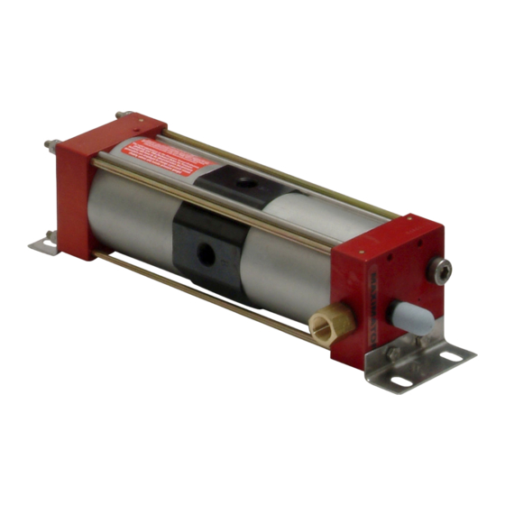
Product description
3.1 Design and function
Explains the internal structure and operational mechanism of the air amplifier.
3.2 Intended use
Defines the specific applications and purposes for which the air amplifier is designed.
3.3 Foreseeable misuse
Lists improper uses that should be avoided to prevent hazards and ensure product longevity.
3.4 Misuse
Warns against unauthorized modifications and technical changes, highlighting potential fatal injuries.
3.5 Ports
Details the various connection ports available on the air amplifier for system integration.
3.6 Technical specifications
Provides detailed technical data, including operating conditions, dimensions, and performance.
Transport, packaging and storage
4.2 Delivery
Details the scope of delivery and lists the included components with their quantities.
4.3 Packaging
Explains how the product is packaged for transport and protection against damage and corrosion.
4.4 Storage
Provides guidelines for storing the product correctly, including temperature and humidity requirements.
Installation
5.1 Prerequisites for installation
Lists the conditions that must be met before installing the product, ensuring a safe setup.
5.2 Air amplifier installation
Provides instructions for physically mounting the air amplifier, including fastening and preferred orientation.
5.3 Installation of connecting lines
Guides on connecting air and control lines to the amplifier, ensuring correct flow and connections.
5.4 Commissioning
Details the steps for putting the air amplifier into operation, including checks and initial startup.
Operation
6.1 Prerequisites for operation
Outlines conditions necessary for safe and proper operation, ensuring system readiness.
6.2 Normal, safe operation
Describes the standard operating procedures for safety, emphasizing normal working conditions.
6.3 Abnormal situations during operation
Advises on handling unexpected events or malfunctions during operation and system behavior.
6.4 Signs indicating the product is no longer safe to use
Lists visual and functional indicators that signal the equipment is unsafe for continued operation.
6.5 Put the air amplifier in a safe state
Explains procedures to render the amplifier safe by depressurizing it, for maintenance or shutdown.
Maintenance
7.1 Maintenance intervals
Specifies recommended schedules for various maintenance activities based on usage and conditions.
7.2 Maintenance work
Details various maintenance tasks, including system inspection, leak testing, cleaning, and repair procedures.
7.3 Spare parts and consumables
Lists available spare parts, part kits, and consumables required for maintenance and repair.
7.4 Accessories and special tools
Mentions available special accessories and tools that can be used with the air amplifier.
7.5 Customer service
Provides contact information for technical support, repairs, and general inquiries.
Troubleshooting
8.1 Drive side
Lists common faults and solutions related to the drive side of the compressor, aiding diagnosis.
8.2 High pressure side
Lists common faults and solutions related to the high-pressure side of the compressor.
Removal and disposal
9.1 Prerequisites for removal and disposal
States the conditions required before removing or disposing of the product to ensure safety.
9.2 Removal
Provides step-by-step instructions for safely removing the air amplifier from its installation.
9.3 Disposal
Gives guidance on the proper and environmentally responsible disposal of the air amplifier.
Use in explosion-prone zones
10.1 General information
Introduces the use of the air amplifier in potentially explosive areas, referencing ATEX regulations.
10.2 Temperature class
Explains the temperature class designation for explosion-prone environments based on operating fluid.
10.3 Operation and maintenance
Covers operation and maintenance specific to explosion-prone zones, addressing static electricity risks.
Need help?
Do you have a question about the GPLV2 and is the answer not in the manual?
Questions and answers