Table of Contents

Related Manuals for MAXIMATOR SPLV2


Summary of Contents for MAXIMATOR SPLV2
- Page 1 Operating, maintenance and repair instructions for ® MAXIMATOR Air Amplifier SPLV2 MAXIMATOR GmbH Walkenrieder Straße 15 37449 Zorge Phone: +49-55 86-80 30 E-Mail: Info@maximator.de Homepage: www.maximator.de Fax: +49-55 86-8 03 40...
-
Page 2: Table Of Contents
Index Function principle of SPLV2 ................3 Technical data ..................... 4 Performance graph....................4 Dimension and Connection Drawing ..............5 Safety ........................6 Pneumatic amplifier..................6 Pneumatic amplifier stations ................ 6 Installation / Operation..................6 Pneumatic amplifiers ..................7 Maintenance......................7 Maintenance tips .................... -
Page 3: Function Principle Of Splv2
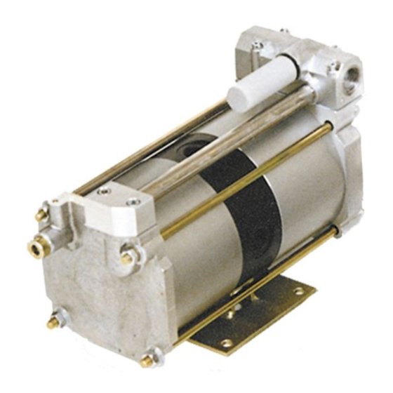
Function principle of SPLV2 MAXIMATOR pneumatic amplifiers are driven by air pressure and increase the pressure according to the given ratio. With a constant pressure in the oneumatic system a brief or locally needed high pressure level can be generated. Pneumatic amplifier stations are equipped with a receiver which reduces pressure fluctuations and have a larger air capacity available immediately. -
Page 4: Technical Data
Technical data Pressure ratio (i) 1 : 2 Air drive pressure (PL) 1-10 bar Max. discharge pressure (PB) 16 bar Max. noise level 79 dB (A) Max. operating temperature (T) 60 °C Air drive connection BSP 1/2” Inlet connection BSP 1/2” Outlet connection BSP 1/2”... -
Page 5: Dimension And Connection Drawing
Dimension and Connection Drawing... -
Page 6: Safety
Safety The MAXIMATOR pneumatic amplifier was constructed in accordance with the established technical regulations as described in the law regulating technical working devices (machines protection law), the accident protection provision and the pressure tank statute. These provisions should also be given attention when installing or using the pneumatic amplifier. -
Page 7: Pneumatic Amplifiers
Pneumatic amplifiers The pneumatic amplifiers can be operated in any installed position. For the pressurized air connector we recommend our control unit ”C 2” with filter, water separator, shutoff valve, pressure regulator, pressure control gauge. As with usual piston seals, pressure pulsation sometimes result from stroke frequency. -
Page 8: Maintenance Tips
All technical and dimensional information subject to change. We reserve the right to alter our products due to technical improvement. Copyright / Patent-right: All MAXIMATOR products are subject to copyrights. The protective rights to DIN 34 have to be observed. Important: All MAXIMATOR pumps, boosters and amplifiers are treated with sislicon free grease during the assembly. -
Page 9: Guarantee
Even smallest impurification may cause serious damage at the precision-machined pneumatic components. All individual pump and compressor parts are available from MAXIMATOR as spare parts. The respective purchase order numbers can be gathered from the drawings attached to each compressor. Typically, there is more than one sealing defective or worn out, hence, we have compiled different sealing kits. -
Page 10: Amplifier Disassembling
Amplifier Disassembling Loosing and disassembling the exhaust muffler (item 14) Unscrew and disassembling of the two screws (item 46). Tool size 6 Disassemble the connection block (item 48) and draw the air tube (item 51) out of the spool valve housing. - Page 11 Loosen the five socket head screws (item 13+12) in the spool valve housing. Disassemble the spool valve housing. Loosen the two socket head screws (item 44 and 43) and disassemble the base plate (item 42).
- Page 12 Loosen the four hexagon nuts (item 56) and remove the u-washer (item 54) and spring washer (item 55) from the stud bolts. Carefully separate the bottom cap (item 46), maybe by means of light hammer taps with a plastic hammer, from the air cylinder (item 26) and disassemble the air tube (item 24).
- Page 13 Carefully separate the top cap (item 1) by means of light taps with a plastic hammer from the air cylinder (item 26). Loosen the two hexagon screws (item 33). Key size : 19 Disassemble the both hexagon nuts (item 33) and u-washers (item 32) from the piston rod (item 27).
- Page 14 Carefully separate the first air cylinder (item 26) from the air separation plate (item 34), maybe by means of light taps with a plastic hammer. Carefully separate the second air cylinder (item 26) in the same way. Pull the piston rod (item 27) out of the air separation plate (item 34) and disassemble the two o-ring (item 31) on both ends.
- Page 15 Remove the piston sealing ring (item 30) from the piston (item 28). Remove the o-ring (item 29) from the piston (item 28). Dismantle the o-ring (item 25) from the bottom cap (item 46).
- Page 16 Dismantle the o-ring (item 23) out of the groove in the bottom cap (item 46). Loosen completely and unscrew the pilot valve screw (item 16). Disassemble the gasket (item 21), the spring (item 18) and pilot valve tappet (item 19).
- Page 17 Dismantle the o-ring (item 25) from the top cap (item 1). Dismantle the o-ring (item 23) out of the groove in the top cap (item 1). Loosen completely and unscrew the pilot valve screw (item 15). Disassemble the gasket (item 21) and the spring (item 18).
- Page 18 Dismantle the pilot valve tappet (item 19) out of the top cap (item 1). Air separation plate (item 34) with the compl. check valves .
-
Page 19: Check Valve Disassembling
11.1 Check valve disassembling Remove the locking ring (item 41). Remove the retainer ring (item 40). Remove the spring holder (item 39). - Page 20 Remove the spring (item 38). Remove the check plate (item 37). Remove the check seat (item 36). Separate the o-ring (item 9) from the check seat (item 36).
- Page 21 Remove the locking ring (item 41). Remove the retainer ring (item 40). Remove the check seat (item 36). Separate the o-ring (item 9) from the check seat (item 36).
- Page 22 Remove the check plate (item 37). Remove the spring (item 38). Remove the spring holder (item 39). Dismantle the o-ring (item 25) from the air separation plate (item 34).
-
Page 23: Spool Valve Disassembling
11.2 Spool valve disassembling Dismantle the locking ring (item 11) at the spool valve housing (item 3) with suitable locking ring pliers. (The ring is located opposite the compressed air inlet). Use a mandrel to force out the spool (item 7) and the spool valve sleeve (item 4) with light strokes of the spool valve housing (item 3). - Page 24 Remove the O rings from the spool and, if applicable, from the spool valve sleeve. Remove the O-ring (item 6) from the sealing cap.
-
Page 25: Amplifier Assembling
Amplifier assembling 12.1 Check valve assembling Grease the two o-rings (item 25) and assemble on the air separation plate (item 34). Assemble the spring holder (item 39) into the air separation plate (item 34). Assemble the spring (item 38) into the air separation plate (item 34). - Page 26 Grease the o-ring (item 9). Assemble the o-ring (item 9) on the check valve seat (item 36). Assemble the valve seat into the air separation plate (item 34). Assemble the retaining ring (item 40) into the air separation plate (item 34). Protect the first check valve by assembling the snap ring (item 41).
- Page 27 Grease the o-ring (item 25). Assemble the o-ring (item 25) on the check valve seat (36). Assemble the check valve seat (item 36) into the air separation plate (item 34). Put the check valve plate (item 37) into the air separation plate (item 34). Put the spring (item 38) into the air separation plate (item 34) and on the on the top side of the check valve plate...
- Page 28 Assemble the spring holder (item 39). Put the retaining ring (item 40) on the top side of the spring holder into the air separation plate (item 34). Protect the second check valve by the snap ring (item 41). picture show compl.
-
Page 29: Air Drive Section Assembling
12.2 Air drive section assembling The right picture show the top cap (item 1). Grease the pilot valve tappet (item 19). Assemble the pilot valve tappet (item 19) in the top cap (item 1). Put the pilot valve spring (item 18) into the pilot hole on the top side of cap (item 1). Assemble the gasket (item 17). - Page 30 Insert and tighten the pilot valve screw (item 15). Grease the o-ring (item 25) and assemble the same on the top cap (item 1).
- Page 31 Grease the o-ring (item 23) and insert it into the top cap (item 1). Insert the damper (item 58) into the top cap (item 1) by means of light taps with a plastic hammer. Completed top cap (item 1).
- Page 32 Bottom cap (item 46). Grease the o-ring (item 25) and mount it on the bottom cap (item 46). Grease and place the o-ring (item 9) into the bottom cap (item 46).
- Page 33 Grease the pilot valve tappet (item 19) and place it into the bottom cap (item 46). Completed bottom cap (item 46). The left picture show the separate parts of air piston consisting of the slide-ring (item 30), the o-ring (item 29) and the piston (item 28). Grease the o-ring (item 29).
- Page 34 Slip the o-ring (item 29) on the piston (item 28). Attach carefully the slide ring (item 30) on the piston (item 28). Grease the two air cylinders (item 26).
- Page 35 Insert the pre-assembled piston into the air cylinder (item 26). Grease the bushing (item 35). Grease the two o-rings (item 31) for the piston rod (item 27).
- Page 36 Attach the o-rings (item 31) on the piston rod (item 27). Insert the pre-assembled piston rod into the air separation plate. Push the air cylinder (item 26) over the piston (item 28).
- Page 37 Attach the washer (item 32) and tighten the nut (item 33). Push the air cylinder (item 26) and the air separation plate (item 34) together until the air cylinder fits closely to the bottom cover. Push the air cylinder (item 26) over the piston (item 28). Attach the washer (item 32).
- Page 38 Push the air cylinder (item 26) and the air separation plate (item 34) together until the air cylinder fits closely to the bottom cover. Tighten the two nuts (item 33) by two keys. Attach the top cap (item 1) and push it to the air cylinder (item 26) until both parts fits closely.
- Page 39 Attach the bottom cap (item 46) and push it to the air cylinder (item 26) until both parts fits closely. Insert the air tube (item 24) and push the bottom cap (item 46) and the top cap (item 1) together. Attach the first (longer tie rod item 53) with u-washer (item 54) and spring washer (item 55) –...
- Page 40 Attach the washer (item 54), the spring washer (item 55) and the nut (item 56). Attach the base plate (item 42). Insert the two socket head screws (item 44) and spring washer (item 43). Tighten the two screws (item 44).
- Page 41 The air amplifier is placed on a workbench for alignment and a soft hammer is used to align the bottom and top cap in parallel. Then tighten the hexagon nuts crosswise with the specified torque. Grease the gasket (item 2) on both sides and attach it onto the top cap (item 1).
-
Page 42: Spool Valve Assembling
12.3 Spool valve assembling Check all components for damage and replace them as required. There must not be any scoring at the spool valve sleeve. Grease all O rings. Slip the O-rings onto the spool (item 7), sealing cap (item 10) and, if applicable, the spool valve sleeve (item 4). - Page 43 Grease the spool valve sleeve well, even when it is still installed. Insert the spool with rotating motions into the spool valve sleeve. If applicable, grease the spool valve housing internally and install the spool valve sleeve with slight rotating motions into the spool valve housing. Re-insert the sealing cap (item 10) into the spool valve housing (item 3) and fasten it with the locking ring (item 11).
- Page 44 Insert the five socket head screws (item 13) with the washer (item 12) into the spool valve housing (item 3). Grease the o-rings (item 50) for the air tube (item 51).
- Page 45 Slip on the o-rings (item 50) for the air tube (item 51) and insert it into the spool valve housing (item 3). Grease and insert the o-ring (item 47) into the bottom cap (item 46). Attach the connection block (item 48) on the bottom cap (item 46).
- Page 46 Place the two socket head screws (item 49) to fasten the connection block (item 48). Re-insert and tighten the exhaust muffler (item 14) into the spool valve housing (item 3). Completed air amplifier type SPLV2.
Need help?
Do you have a question about the SPLV2 and is the answer not in the manual?
Questions and answers