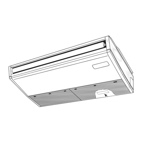
Table of Contents
Advertisement
Advertisement
Table of Contents

Summarization of Contents
1 REFERENCE MANUAL
1-1. OUTDOOR UNIT'S SERVICE MANUAL
Service manuals for outdoor units.
1-2. TECHNICAL DATA BOOK
Technical data for units.
2 SAFETY PRECAUTION
MEANINGS OF SYMBOLS DISPLAYED ON THE UNIT
Explanation of symbols used on the unit.
2-1. ALWAYS OBSERVE FOR SAFETY
Essential safety rules for operation.
2-2. CAUTIONS RELATED TO NEW REFRIGERANT
Precautions for handling new refrigerants.
3 PARTS NAMES AND FUNCTIONS
3-1. INDOOR UNIT
Identification of indoor unit components.
3-2. WIRELESS REMOTE CONTROLLER (OPTION)
Functions of the wireless remote controller.
3-3. WIRED REMOTE CONTROLLER (OPTION)
Functions of the wired remote controller.
4 SPECIFICATIONS
4-1. SPECIFICATIONS
Detailed technical specifications for indoor units.
4-2. FRESH AIR INTAKE AMOUNT & STATIC PRESSURE CHARACTERISTICS
Airflow and pressure characteristics curves.
6 OUTLINES AND DIMENSIONS
PCA-M35KA and PCA-M50KA Dimensions
Physical dimensions for PCA-M35KA and PCA-M50KA.
PCA-M60KA and PCA-M71KA Dimensions
Physical dimensions for PCA-M60KA and PCA-M71KA.
PCA-M100KA, PCA-M125KA, and PCA-M140KA Dimensions
Physical dimensions for PCA-M100KA, PCA-M125KA, PCA-M140KA.
7 WIRING DIAGRAM
Wiring Diagrams for Various Models
Electrical wiring diagrams for different unit models.
8 REFRIGERANT SYSTEM DIAGRAM
Refrigerant System Diagrams for Various Models
Diagrams illustrating the refrigerant circuit.
9 TROUBLESHOOTING
9-1. TROUBLESHOOTING
Summary of self-diagnosis and actions.
9-2. MALFUNCTION-DIAGNOSIS METHOD BY REMOTE CONTROLLER
Procedure for diagnosing malfunctions via remote controller.
Error Code Patterns and Symptoms
Tables detailing error codes, patterns, and symptoms.
9-4. TROUBLESHOOTING OF PROBLEMS
Detailed troubleshooting steps for common issues.
9-3. SELF-DIAGNOSIS ACTION TABLE
Table listing self-diagnosis codes, causes, and countermeasures.
9-5. EMERGENCY OPERATION
Procedures for emergency operation of the unit.
9-6. HOW TO CHECK THE PARTS
Methods for checking specific unit components.
9-7. TEST POINT DIAGRAM
Diagram showing test points on the controller board.
10 FUNCTION SETTING
10-1. UNIT FUNCTION SETTING BY THE REMOTE CONTROLLER
Setting unit functions using the remote controller.
11 SPECIAL FUNCTION
11-1. ROTATION FUNCTION (AND BACK-UP FUNCTION, 2ND STAGE CUT-IN FUNCTION)
Functions for unit rotation and backup operation.
12 DISASSEMBLY PROCEDURE
1. Removing the air intake grille
Steps to remove the air intake grille.
2. Removing the indoor controller board and the electrical box
Steps to remove the indoor controller and electrical box.
3. Removing the room temperature thermistor (TH1)
Steps to remove the room temperature thermistor.
4. Removing the fan motor and right side fan
Steps to remove the fan motor and fan.
5. Removing the fan (3 connection)
Steps to remove the fan assembly.
6. Removing the side panel
Steps to remove the side panel.
7. Removing the vane motor
Steps to remove the vane motor.
8. Removing the under panel
Steps to remove the under panel.
9. Removing the drain pan
Steps to remove the drain pan.
10. Removing the pipe temperature thermistors/liquid (TH2) and condenser/evaporator temperature thermistor (TH5).
Steps to remove temperature thermistors.
11. Removing the guide vane
Steps to remove the guide vane.
12. Removing the Auto vane
Steps to remove the auto vane assembly.
13. Removing the heat exchanger
Steps to remove the heat exchanger unit.


Need help?
Do you have a question about the Mr.SLIM PUMY-P140YKM and is the answer not in the manual?
Questions and answers