Table of Contents
Advertisement
Advertisement
Table of Contents

Related Manuals for Sollatek FreoCom FCA23 Series


Summary of Contents for Sollatek FreoCom FCA23 Series
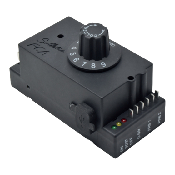
- Page 1 FCAx3 Advanced Electronic Temperature Controller With Energy Saving, Defrost, and Plug-in Connectivity Options USER MANUAL Important: This manual contains important safety instructions. Before using this product please read all instructions carefully. Keep this manual handy for reference.
- Page 2 FIT FOR PURPOSE The Sollatek device must only be used for the purpose and functions described in this manual. As each application requires a different configuration and setup, no liability is accepted by Sollatek UK Ltd for the correct operation of the final equipment.
- Page 3 Find out the arrangements that exist on-site for first aid, and who is responsible for taking charge of these. DISPOSAL Sollatek devices are subject to the EU directive 2012/19/EU and may also be subject to other national legislation for the safe disposal of e-waste.
-
Page 4: Table Of Contents
CONTENTS 1. INTRODUCTION 10. PARAMETERS 1.1 DESCRIPTION 10.1 HARDWARE CONFIGURATION 1.2 MODEL VARIANTS 10.2 RELAY CONFIGURATION (RELAY #2/#3) 1.3 LED INDICATORS 10.3 TEMPERATURE CONTROL 10.4 ENERGY SAVING (TEMPERATURE SET-BACK) 2. FUNCTION 10.5 DELAYS AND TIMERS 2.1 TEMPERATURE CONTROL 10.6 DEFROST FUNCTION 2.2 ENERGY SAVING 10.7 VOLTAGE PROTECTION 2.3 DEFROST CONTROL... -
Page 5: Introduction
The “x” in the part number FCAx3 indicates the number of controllable outputs. There are three models available: FCA13 = 1 relay, 16 Amp (Compressor) FCA23 = 2 relays, 16 Amp (Compressor) + 5 Amp (Aux1) FCA33 = 3 relays, 16 Amp (Compressor) + 2x 5 Amp (Aux1 & Aux2) sollateksupport@sollatek.com 5 FCAx3 USER MANUAL... -
Page 6: Led Indicators
1.3 LED INDICATORS Mains Voltage Compressor Description L E D s O f f . V o l t a g e B a d . C o o l i n g D e m a n d O f f . V o l t a g e B a d . N o C o o l i n g D e m a n d W a i t P e r i o d ( i n t e l l i g e n t t i m e d e l a y ) . -
Page 7: Function
The FCAx3 will automatically adjust the reconnection period meaning the cooler will never be off for longer than required. sollateksupport@sollatek.com 7 FCAx3 USER MANUAL... -
Page 8: Operation
3. OPERATION 3.1 STANDARD REGULATING MODE CUT IN Temperature Probe Pull down CUT OUT Compressor Evaporator Fan Defrost Mains Voltage Time 8 +44 (1753) 214 500 FCAx3 USER MANUAL... - Page 9 9 FCAx3 USER MANUAL...
-
Page 10: Defrost Mode
3.2 DEFROST MODE 3.2.1 STANDARD DEFROST Depending on the requirement, defrost can be triggered by either using the temperature or/and by time, when both settings are enabled, whichever event happens first will trigger or end the defrost cycle. The FCAx3 has a minimum defrost duration and minimum duration between defrost cycles which must be satisfied before it will act no matter the status of the other parameters. -
Page 11: Energy Saving Mode
Temperature CUT OUT Energy Saving is activated Energy Saving is terminated Compressor OPEN Door Switch CLOSE Door Open Duration to Exit Engery Saving Door Close Duration to Start Energy Saving Engery Saving Max Duration Time sollateksupport@sollatek.com 11 FCAx3 USER MANUAL... -
Page 12: Features
4. FEATURES 4.1 TEMPERATURE BLIND TIME The software will ignore the sensor temperature reading for the first few seconds (a pre-set value of 10 seconds) after the compressor is switched on. This is to prevent short-term thermal effects such as those caused by the fan starting to operate causing disconnection. -
Page 13: Timesave™ Function
Voltage BAD Voltage GOOD Disconnection Period Intelligent Time (2 mins) Delay (1 min) Compressor Voltage GOOD Voltage BAD Voltage GOOD Disconnection Period (7 mins) Compressor *Above illustrations use intelligent time delay set to 3 minutes sollateksupport@sollatek.com 13 FCAx3 USER MANUAL... -
Page 14: Intelligent Blackout Time Delay
FCAx3 controllers are equipped with Bluetooth capability, enabling them to connect to the Sollatek Smart device Application. The Sollatek App has extensive cooler management capabilities providing technicians with all the tools to view and upload controller status and event data. -
Page 15: Connectivity Device
Remote Cooler Shut-down - In the event the cooler is stolen, disable the cooler so it cannot be used. Once the cooler is recovered the cooler can then be enabled. The transmission interval of cooler health data can be configured via the Sollatek Smart Device Application. Health data will not be transmitted while being powered by the battery. -
Page 16: Installation
5. INSTALLATION 5.1 FCAx3 DIMENSIONS 5.2 MOUNTING INSTRUCTIONS WARNING! FCAx3 MUST be mounted with terminals in an isolated area, either in a plastic or earthed metal case. 1. Mark and drill holes for the dial shaft and mounting screws in the surface where the FCAx3 is to be mounted according to the panel cut-out. - Page 17 Note: The port is recessed, and the cable has a rubber boot so when a device is connected, the IP rating is maintained. Plug the other end of the connector cable into the connector on the device. sollateksupport@sollatek.com 17 FCAx3 USER MANUAL...
-
Page 18: Testing Procedure
6. TESTING PROCEDURE 6.1 THERMOSTATIC FUNCTION Connect the FCAx3 to a source of variable AC voltage such as a Variac and set the temperature dial to 9. Adjust the output of the Variac to a good starting voltage (within the acceptable limits) and power it on. The yellow LED will turn ON and stay on if the temperature detected by the regulation temperature probe (Probe#1) is below the cut-in temperature. -
Page 19: Voltage Protection Function
• The High Voltage Blind Time is 0.5 seconds. Note: Low/high Blind Times are Sollatek’s recommended timings. Blind times are configurable in the desktop configuration interface so actual timings may differ from the times stated depending on your settings. Tip: During testing, short the test pins to bypass the set time delay and force the FCAx3 to operate immediately sollateksupport@sollatek.com 19... -
Page 20: Alarms & Errors
7. ALARMS & ERRORS 7.1 FREQUENCY MONITORING AND ERROR DETECTION The FCAx3 dynamically measures the frequency of the mains supply and reacts accordingly. If the mains supply frequency is too low or too high, the FCAx3 will then disconnect the compressor and indicate an error signal through the LEDs. The FCAx3 can auto-recover once the frequency is within acceptable limits. -
Page 21: Defrost Probe Error Detection
7.4 INTERNAL FAULT DETECTION If an internal fault within the FCAx3 is detected, it is reported through the LED indicators. If the fault does not automatically clear and resumes normal operation, then please contact Sollatek for help and advice. sollateksupport@sollatek.com 21... -
Page 22: Configuration
The installer wizard window will appear on the screen. Follow the on-screen instructions in the wizard and enter the company name and password, as provided by Sollatek. The files and data will be automatically extracted without any user intervention. Progress will be indicated on the status bar within the wizard. - Page 23 * When you Generate F/W or Save As you will be asked if you want a specification sheet saving. This is a spreadsheet of all the parameters and set values. 8.1.4 DEVICE SELECTION The desktop interface can be used to program multiple Sollatek Controllers. Before proceeding to make any changes to parameters, ensure FCAx3 is selected from the product family menu within the hardware configuration section.
-
Page 24: Remote Configuration
Connect the FCAx3 interface cable to the micro-USB port on the side of the FCAx3 and the USB port on your computer. WARNING! Only a Sollatek isolated interface cable is to be used, unapproved or unisolated cables will cause damage to the FCAx3 and the computer. -
Page 25: Programming
9. PROGRAMMING FCAx3 firmware and configuration can be updated via the Sollatek Product Programmer device (SPP02). The SPP02 can be programmed directly from the controller configuration software or the SPP visual programmer (refer to SPP Visual Programmer User Instructions for details on this method) and then uploaded to the FCAx3. - Page 26 Downloading Parameters from the Parameter Configuration Window. Open and edit/create a configuration to match your requirement. Plug the SPP02 into the USB port in your computer, if plugging in for the first time please wait for all the drivers to be installed before proceeding, this may take several minutes.
-
Page 27: Parameters
Minutes 1 to 255 Cycling Off Time (mins) Minutes 1 to 255 On, Off, Cycling, Heater, On/Cycling, Same as Operation When Probe#3 if Faulty Comp, Light Control Cycling On Time (mins) Minutes 1 to 255 sollateksupport@sollatek.com 27 FCAx3 USER MANUAL... - Page 28 Cycling Off Time (mins) Minutes 1 to 255 Operation When Door is Open Normal, Off, ON Door Open Response Time (secs) Seconds N/A, 1 to 255 Door Close Response Time (secs) Seconds N/A, 1 to 255 Operation When in Post Drip Down Recovery On or Off Type of Load Select the type of load connected to the relay.
-
Page 29: Temperature Control
-40 to +45°C / -40 to +113°F Set-back Setting Cut-in Temp (marking 0 to 9) °C / °F -40 to +45°C / -40 to +113°F Cut-out Temp (marking 0 to 9) °C / °F -40 to +45°C / -40 to +113°F sollateksupport@sollatek.com 29 FCAx3 USER MANUAL... - Page 30 Regulation Temperature Probe Select the temperature probe used as the regulation temperature probe. Probe 1 = Probe connected to P1. Probe 2 = Probe connected to P2. Only available if 2 is selected from “Number of Temperature Probes”. Probe 3 = Probe connected to D-SW. Only available if 3 is selected from “Number of Temperature Probes”. Temperature Blind Time The duration that the regulation temperature probe reading will be ignored after the compressor switches ON.
-
Page 31: Energy Saving (Temperature Set-Back)
Note: Protection delay must be satisfied whenever the compressor is switched off regardless of the reason (high/low voltage, temperature below cut-out, defrost, faulty probe, power down, etc). Protection Delay Initial Bypass Count (for use in testing only) sollateksupport@sollatek.com 31 FCAx3 USER MANUAL... -
Page 32: Defrost Function
The number of controller start-ups, in which the Compressor Relay OFF Protection Delay will be ignored. This will result in the compressor turning ON as soon as the FCAx3 is powered up. Note: The Compressor Relay OFF Protection Delay will still be respected during operation. Delay Between Loads The minimum time delay between one relay turning ON and another being allowed to turn ON. - Page 33 Defrost Start Time (if enabled). aCC: Accumulated Time = The defrost start timer will count only when the compressor is ON and stops counting (not resetting) sollateksupport@sollatek.com 33 FCAx3 USER MANUAL...
- Page 34 when the compressor is OFF, resulting in counting the accumulated durations during which the compressor has been ON. The defrost will start when the timer value exceeds the value of Defrost Start Time (if enabled). Cnt: Continuous Timer = The defrost start timer will count only when the compressor is ON and resets to zero whenever the compressor is OFF.
-
Page 35: Voltage Protection
Door Switch Open Persistence Duration (secs) Seconds N/A, 1 to 255 Door Switch Close Persistence Duration (secs) Seconds N/A, 1 to 255 Compressor Operation when Door Switch is Open Select the compressor operation when a door event occurs. sollateksupport@sollatek.com 35 FCAx3 USER MANUAL... -
Page 36: Heater Function
Normal = The compressor ignores the door event and resumes normal operation. OFF = The compressor will turn OFF and remain OFF during a door open event. When the door is closed, the compressor will resume normal operation. Door Switch Open Persistence Duration The duration that the door remains open before the compressor will switch OFF. -
Page 37: Specification
Type/version BLE 4.1 RF Power Output -20 dBm to +4 dBm Frequency 2.4 GHz ISM Connectivity Eddystone, iBeacon & connection to the Sollatek Smart Device Application Bluetooth Standard IEEE 802.15.1 Battery Type Rechargeable Lithium polymer Nominal Voltage Capacity 5.5 mAh Typical Run Time From a Single Charge RTC Only: Approx. - Page 38 Data / Programming Micro USB-B ENVIRONMENTAL IP Rating Electronics: IP65 (PCB Encapsulated) Operating Temperature 0 to +50°C (32 to +122°F) Operating Humidity <90% RH non-condensing Storage Temperature -40 to +60°C (-40 to +140°F) CERTIFICATION / STANDARDS Product Certification CE, UL60730-1 and UL60730-2-9 (file no: E242907), IEC 60730-1, IEC 60730-2-9, Hazloc approved, ANSI 2-2018 Disconnection Type Type 1.B...
-
Page 39: Accessories
22/08/2018 Initial Version Bhargav Mistry 20/12/2019 Rebrand, all sections updated Bhargav Mistry 28/05/2021 Section 1.3, 3, 8 & 10 updated Neville Barreto 04/05/2023 Rebrand, all sections updated Neville Barreto 06/09/2023 Section 10.2 updated Neville Barreto sollateksupport@sollatek.com 39 FCAx3 USER MANUAL... - Page 40 The information in this document has been carefully checked Sollatek (UK) Ltd. Sollatek House, Waterside Drive, Langley, Slough SL3 6EZ UK and is believed to be accurate. Nevertheless Sollatek assumes no responsibility for any errors or omissions.
Need help?
Do you have a question about the FreoCom FCA23 Series and is the answer not in the manual?
Questions and answers