Table of Contents
Advertisement
Quick Links
Advertisement
Table of Contents

Related Manuals for Sollatek AVR


Summary of Contents for Sollatek AVR
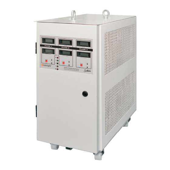
- Page 1 The Sollatek Three Phase Automatic Voltage Regulator (AVR) www.s ol la tek . c om Instruction Manual Issue: July 2021 Important: This manual contains important safety instructions.
-
Page 2: Table Of Contents
The unit should be positioned such that a free flow of air is available. It is especially important to Trouble Shooting ensure that cooling fan outlets are free from obstruction. A free space of at least 300mm should be Safety left in all directions around the AVR. False Starting Shut Down Cable and terminals... -
Page 3: Circuit Breakers
See diagram 2.6.1 the door of the AVR should indicate a valid output voltage. If this is not the case switch off the power immediately and refer to the troubleshooting section of this manual. The AVS indicators on the door (if Outgoing connections fitted) should show ‘on’... -
Page 4: Avs Function
21kVA. The parameters monitored by the Three Phase AVS are: The standard Three Phase AVR provides an output which is stable to within + 4% given an input a) Value of the Mains Voltage voltage variation of + 27% from a defined nominal. Although it is likely that voltage stability of + 4% The normal condition is when the values of the mains voltage of all the phases are within certain will meet most customers’... -
Page 5: Surge Arrester
This ensures that the supply to the AVR cannot be re-connected unintentionally by component failure If it is found that the AVR keeps trying to start but turns off immediately, this is most likely to be due or supply disruptions. This is particularly important if the bypass is used to enable maintenance to be to poor wiring to the AVR or in the building. -
Page 6: Error Mode
ENGLISH THREE PHASE AUTOMATIC VOLTAGE REGULATOR Issue: July 2021 Error Modes If the AVR has shut down it is possible to observe the LEDs on the PCBs within the unit. These can display two different error modes. ظفحت یک �تق... - Page 7 � ے ہک وہا اک زگر نکمم وہ۔ اس ارم وک ئ ازاہل صقن اکری ازاہل صقن اکری �003 یک اخیل ہگج وھچڑی اجین اچ � ہ � یmm ےک رگد رہ تمس م ی مک از مکAVR راکوٹ ےس اپک وہں۔ ے۔ ظفحت ن...
- Page 8 � ج یک � ج م ی � ےک دروازے رپ ےگلAVR االطق ک ی ا اج اتکس ےہ۔ ا ِ ن ٹپ اپور ےک االطق ےک دعب زز رپ درتس آؤٹ ٹپ وو ل وو � ے ہک امتم رٹ م� ی...
- Page 9 ی ٹ + 27% � ج ےک ا� ی ا� ی ا آؤٹ ٹپ اقمم رفامہ رکات ےہ وجہک ا� ی وعض رکدہ ادنازے ےک اقمےلب م ی ا ِ ن ٹپ ووAVR ز : زز �ی � ہ ی...
- Page 10 طلغ ادتباء � ی اAVR آاغز یک وکشش رکات راتہ ےہ ل ی ن وفر ا ً یہ دنب وہ اجات ےہ، وت تہب دح کت ااکمن ےہ ہک ا� ی اAVR ارگ �ی د� ی ا اجےئ ہک...
-
Page 11: Appendix 1: General Arrangement
صقن ومڈز APPENDIX 1: General Arrangement اک اشمدہہ نکمم ےہ۔ �ی دو فلتخم صقن ومڈز ڈےلپس رک ےتکس � ہ ی ۔LEDs م یPCBs دنب وہ گ ی ا ےہ وت �ی وٹن ےک ادنر وموجدAVR ارگ ئ... -
Page 12: Appendix 2: Bypass Installation
Positioning http://www.sollatek.com The bypass should be installed directly next to the AVR to allow wiring between the two units. Both units should be positioned as closely as possible to the incoming supply access. See AVR manual for further positioning requirements. - Page 13 THREE PHASE AUTOMATIC VOLTAGE REGULATOR Issue: July 2021 THREE PHASE AUTOMATIC VOLTAGE REGULATOR Issue: July 2021 APPENDIX 3 System topology diagrams 1. Main AVR 2. Main power PCBs 3. Cooling fans 4. LCD Display 5. Distribution surge protection 6. Fuse PCB 7.
- Page 14 Checked by Approved by - date Date Scale 185001 14/3/01 Title: Units 4/5, Trident Ind. Est., Blackthorne Road, Poyle, AVR cooling fans Slough, Berks. SL3 0AX. DWG. No. Edition Sheet Tel: 01753 688300 1850.01 Fax: 01753 685306 Page: 25 Page: 26...
- Page 15 THREE PHASE AUTOMATIC VOLTAGE REGULATOR Issue: July 2021 THREE PHASE AUTOMATIC VOLTAGE REGULATOR Issue: July 2021 THREE PHASE AUTOMATIC VOLTAGE REGUL ATOR Issue: Feb 2002 THREE PHASE AUTOMATIC VOLTAGE REGUL ATOR Issue: Feb 2002 Page: 28 Page: 27 Page 28 Page 29...
- Page 16 Approved by - date Filename Date Scale 184701 13/3/01 Units 4/5, Trident Ind. Est., Title: Blackthorne Road, Poyle, AVR fuse distribution PCB's Slough, Berks. SL3 0AX. DWG. No. Edition Sheet Tel: 01753 688300 1847.01 Fax: 01753 685306 Page: 29 Page: 30...
- Page 17 AVS delay setting _______________________________________ 20% full load. AVS must be operational for this test. 11. Connect two phases to the input of the AVR. Connect the third phase via the variac. Adjust the variac voltage Inspected by (SUKL Engineer) _______________________________________ to 230V.
- Page 18 7. Fitting replacement PCB is a reversal of the above procedure. Micro 8. It is essential that the On Site AVR Test Procedure following Maintenance/Repair for replaced power PCBs is followed before the AVR is put back on-line. Input LEDs Live-Out Power PCB replacement procedure (Multiple PCBs per Stack –...
- Page 19 Ensure the AVR is isolated from the supply and load before commencing 1. On certain AVR models it will be necessary to remove the rear panel to access the AVS PCB. 2. Note all wiring colours and positions and AVS settings.
- Page 20 The AVR should be disconnected from Mains and Load before commencing this test. 17. Increase the variac until the AVR output is 241Vac +/- 0.5V. SLOWLY turn P1 anticlockwise until the output voltage drops (to approx. 222V). LED LD2 should now be on.
- Page 21 2. Increase input volts to 230V. 3. Two LEDs on selected phase of DSP should be illuminated. The DSP is situated at the rear of the AVR. It may be necessary to remove the back panel to access the DSP.
- Page 22 THREE PHASE AUTOMATIC VOLTAGE REGULATOR Issue: July 2021 THREE PHASE AUTOMATIC VOLTAGE REGULATOR Issue: July 2021 Page 42 Page 43...
- Page 23 THREE PHASE AUTOMATIC VOLTAGE REGULATOR Issue: July 2021 THREE PHASE AUTOMATIC VOLTAGE REGULATOR Issue: July 2021 Page 44 Page 45...
- Page 24 THREE PHASE AUTOMATIC VOLTAGE REGULATOR Issue: July 2021 THREE PHASE AUTOMATIC VOLTAGE REGULATOR Issue: July 2021 Page 46 Page 47...
- Page 25 C20-26 - 2 & 3 WAY = 4.7UF REV: DATE: 14.03.2000 ENG: C20-26 - 4 & 5 WAY = 10UF PROJECT: ST1654D AVR TRIAC DRIVE CIRCUIT COMPANY: SOLLATEK (UK) LIMITED ADDRESS: 4 TRIDENT INDUSTRIAL ESTATE CITY BLACKTHORNE ROAD, POYLE, SLOUGH...
- Page 26 ©Sollatek (UK) Limited 2021. All Rights Reserved. SOLLATEK Sollatek (UK) Ltd. Sollatek House, Waterside Drive, Langley, Slough SL3 6EZ UK and the SOLLATEK device are the trade marks of the Sollatek group of companies. 21/07/2021 AVR 3ph Instructions English/Urdu July 2021 w w w.
Need help?
Do you have a question about the AVR and is the answer not in the manual?
Questions and answers