Advertisement
Quick Links
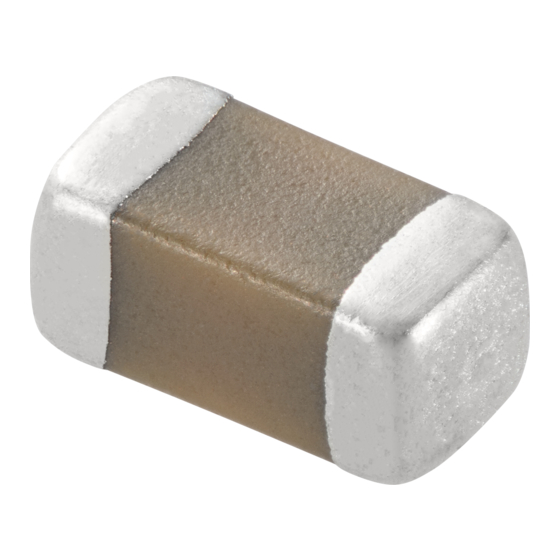
Chip Monolithic Ceramic Capacitor for General
GRM32ER71J106KA12_ (1210, X7R:EIA, 10uF, DC63V)
_: packaging code
1.Scope
This product specification is applied to Chip Monolithic Ceramic Capacitor used for General Electronic equipment.
2.MURATA Part NO. System
(Ex.)
GRM
32
(1)L/W
Dimensions
3. Type & Dimensions
(1)-1 L
(1)-2 W
3.2±0.3
2.5±0.2
4.Rated value
(3) Temperature Characteristics
(Public STD Code):X7R(EIA)
Temp. coeff
or Cap. Change
-15 to 15 %
5.Package
mark
(8) Packaging
f180mm Reel
L
EMBOSSED W8P4
f330mm Reel
K
EMBOSSED W8P4
Product specifications in this catalog are as of Mar.4,2016,and are subject to change or obsolescence without notice.
Please consult the approval sheet before ordering.
Please read rating and !Cautions first.
GRM32ER71J106KA12-01
E
R7
(2)T
(3)Temperature
Dimensions
Characteristics
(2) T
e
2.5±0.2
0.3 min.
(4)
Rated
Temp. Range
Voltage
(Ref.Temp.)
-55 to 125 °C
DC 63 V
(25 °C)
Packaging Unit
1000 pcs./Reel
4000 pcs./Reel
1J
106
(6)Capacitance
(4)Rated
(5)Nominal
Tolerance
Voltage
Capacitance
(Unit:mm)
g
1.0 min.
Specifications and Test
(6)
(5) Nominal
Capacitance
Capacitance
Tolerance
10 uF
±10 %
1
Reference Sheet
K
A12
L
(7)Murata's
(8)Packaging
Control Code
Code
Methods
(Operating
Temp. Range)
-55 to 125 °C
Advertisement

Summarization of Contents
Specifications and Test Methods
1. Rated Voltage
Specifies the test method and definition for rated voltage.
2. Appearance
Defines the visual inspection criteria for the capacitor's appearance.
3. Dimension
Refers to the specified dimensions for the capacitor.
4. Voltage proof
Details the test method for voltage proof.
5. Insulation Resistance (I.R.)
Specifies the test method for insulation resistance.
6. Capacitance
Refers to the capacitance value as shown in rated value.
7. Q or Dissipation Factor (D.F.)
Outlines the test methods for Q factor and dissipation factor.
8. Temperature Characteristics of Capacitance
Describes capacitance change based on temperature variations.
9. Adhesive Strength of Termination
Specifies the test for adhesive strength of the capacitor termination.
1.Tape Carrier Packaging
1.1 Minimum Quantity(pcs./reel)
Specifies the minimum quantity of capacitors per reel for different packaging types.
1.2 Dimensions of Tape
Provides dimensions related to tape carrier packaging.
2. Others
2-1. In an Emergency
Actions to take in case of equipment malfunction or fire.
2-2. Disposal of waste
Guidelines for proper disposal of used capacitors.
2-3. Circuit Design
Recommendations for fail-safe functions and product certification.
1.PCB Design
1. Notice for Pattern Forms
Guidelines for PCB pattern design to prevent chip cracking.
3. Board Design
2.Adhesive Application
Guidelines for applying adhesive to ensure proper chip bonding.
3.Adhesive Curing
Procedures for curing adhesive to maintain insulation resistance.
4.Flux (for Flow soldering)
Recommendations for flux type and usage in flow soldering.


Need help?
Do you have a question about the GRM32ER71H475KA88L and is the answer not in the manual?
Questions and answers