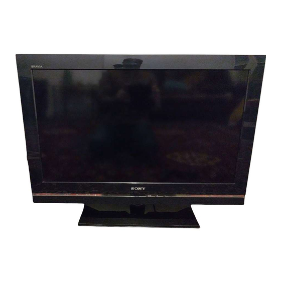
Sony KDL-40V5800 Service Manual
Flat panel color tv
Hide thumbs
Also See for KDL-40V5800:
- Operating instructions manual (28 pages) ,
- Instruction & operation manual (119 pages) ,
- Operating instructions manual (186 pages)
Summarization of Contents
General Information and Specifications
Lead-Free Soldering Caution
Safety guidelines for servicing circuit boards using lead-free solder.
UK Plug Warning
Safety information and instructions for UK mains plugs.
LCD Panel Caution
Precautions for handling the LCD panel during servicing.
Power and Other Specifications
Details on power requirements, screen size, and power consumption.
Dimensions and Mass Specifications
Technical data on unit dimensions and weight for different models.
System and Input/Output Specifications
Information on TV system, panel, color, channel coverage, and I/O jacks.
PC Input Signal Reference Chart
Chart detailing supported PC input resolutions and frequencies.
Disassembly Procedures
Rear Cover Removal and Installation
Step-by-step guide for removing and reinstalling the rear cover.
Stand Assembly Removal
Procedure for detaching the television's stand assembly.
Under Cover Removal
Steps for removing the internal under cover component.
Loudspeaker Removal
Instructions for disconnecting and removing the loudspeakers.
BA Board Removal
Procedure for removing the BA main board.
D5N Board Removal (52 inches)
Steps to remove the D5N board for 52-inch models.
D6N Board Removal (52 inches)
Steps to remove the D6N board for 52-inch models.
G2 Board Removal (32 inches)
Procedure for removing the G2 board for 32-inch models.
G4 Board Removal (37 inches)
Steps to remove the G4 board for 37-inch models.
G5 Board Removal (52 inches)
Procedure for removing the G5 board for 52-inch models.
HL1A Board Removal
Steps for removing the HL1A board.
HSN Board Removal
Procedure for removing the HSN board.
IP1 Board Removal (40 inches)
Steps to remove the IP1 board for 40-inch models.
IP2 Board Removal (46 inches)
Procedure for removing the IP2 board for 46-inch models.
TUS Board Removal
Steps for removing the TUS board.
Service Menus and Adjustments
Entering Service Mode
Instructions on how to access the TV's service mode.
Changing TVM Data Settings
Guide to modifying TVM (Television Module) data parameters.
Writing TVM Data
Process for saving modified TVM data to the unit.
Diagrams and Schematics
System Block Diagram
Overview of the television's main functional blocks and interconnections.
Circuit Board Location Guide
Visual identification of main circuit boards within the TV.
Schematic and Printed Wiring Diagrams
References to detailed electronic schematics and board layouts.
Exploded Views
Chassis Exploded View
Detailed breakdown of the TV chassis with part identification.
Bezel and Stand Assembly Exploded View
Exploded diagram of the TV's front bezel and stand components.
Rear Cover and Power Supply Cords Exploded View
Breakdown of the rear cover, ports, and power supply cords.
Electrical Parts List
BA Board Complete Parts List
Comprehensive list of parts for the BA board.
HL1A Board Complete Parts List
List of all components for the HL1A board.
HSN Board Complete Parts List
List of all components for the HSN board.
TUS Board Complete Parts List
List of all components for the TUS board.
Accessories and Connectors List
List of included accessories and various connectors.
Remote Commander List
Part numbers and details for remote controllers.


Need help?
Do you have a question about the KDL-40V5800 and is the answer not in the manual?
Questions and answers