BENDIX TU-FLO 750 COMPRESSOR Manual
Hide thumbs
Also See for TU-FLO 750 COMPRESSOR:
- Service data (16 pages) ,
- Installation information (2 pages)
Table of Contents
Advertisement
®
®
®
Bendix
Tu-Flo
DISCHARGE
VALVE STOP
DISCHARGE
VALVE
DISCHARGE
VALVE SEAT
CONNECTING
ROD
®
BENDIX
TU-FLO
(CROSS SECTION)
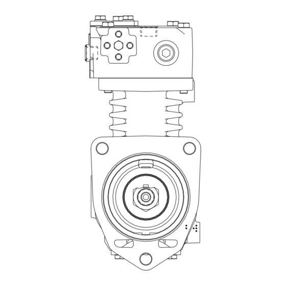
DESCRIPTION
The function of the air compressor is to provide and main-
tain air under pressure to operate devices in the air brake
and/or auxiliary air systems. The Tu-Flo
is a two cylinder single stage, reciprocating compressor
with a rated displacement of 16.5 cubic feet per minute at
1,250 RPM.
The compressor assembly consists of two major
subassemblies, the cylinder head and the crankcase. The
Cylinder Head is an iron casting which houses the inlet,
discharge, and unloader valving. (See Figure 1.) The cylinder
head contains the air inlet port and is designed with both
top and side air discharge ports. Three water coolant ports
provide a choice of coolant line connections. Governor
mounting surfaces are provided at both the front and the
rear of the cylinder head. The head is mounted on the
crankcase and is secured by six cap screws. The Tu-Flo
750 compressor is designed such that the cylinder head
can be installed in one of two positions which are 180 degrees
apart. The crankcase houses the cylinder bores, pistons,
crankshaft and main bearings, and provides the flange or
base mounting surface.
750 Air Compressor
UNLOADER
COVER
DISCHARGE
VALVE SPRING
®
750 AIR COMPRESSOR
®
750 compressor
AIR DISCHARGE
WATER
INLET
GOVERNOR
MOUNTING
PAD
PISTON
BENDIX
CYLINDER
HEAD
®
END VIEW OF CYLINDER HEAD
CYLINDER
HEAD
®
®
TU-FLO
750 AIR COMPRESSOR
(EXTERIOR)
UNLOADER
WATER OUTLET
AIR INLET
CRANKCASE
PIECE NO.
TAG
INLET VALVE
INLET VALVE
SEAT
INLET
INLET VALVE
SPRING
1
Advertisement
Table of Contents
Troubleshooting

Related Manuals for BENDIX TU-FLO 750 COMPRESSOR


Summary of Contents for BENDIX TU-FLO 750 COMPRESSOR
- Page 1 ® ® ® Bendix Tu-Flo 750 Air Compressor DISCHARGE UNLOADER CYLINDER AIR DISCHARGE VALVE STOP COVER HEAD WATER OUTLET DISCHARGE VALVE WATER INLET DISCHARGE AIR INLET VALVE SEAT CRANKCASE DISCHARGE VALVE SPRING GOVERNOR CRANKCASE PISTON RINGS MOUNTING PISTON CONNECTING CRANKSHAFT PIECE NO.
-
Page 2: Intake And Compression Of Air (Loaded)
(Reference Figure 3.) created between the top of the piston and the cylinder head, causing the inlet valve to move off its seat and open. (Note: TU-FLO 750 COMPRESSOR The discharge valve remains on its seat.) Atmospheric air is BENDIX NO. -
Page 3: Non-Compression Of Air (Unloaded)
UNLOADER DISCHARGE GOVERNOR PISTON GOVERNOR DISCHARGE PORT PORT PORT PORT INLET PORT INLET PORT INLET VALVE INLET HELD OPEN VALVE DISCHARGE DISCHARGE BY UNLOADER OPEN VALVE VALVE PISTON CLOSED CLOSED PISTON MOVING DOWN FIGURE 4 - OPERATIONAL-LOADED (INTAKE) FIGURE 6 - OPERATIONAL-UNLOADED ernor closes and exhausts the air from above the unloader GOVERNOR DISCHARGE... -
Page 4: Duty Cycle
2 of Table A in the Troubleshooting section) assumes a compressor with a normal (less than 25%) duty cycle, THREAD operating in a temperate climate. See Bendix and/or other air dryer manufacturer guidelines as needed. FIGURE 6B - DISCHARGE LINE SAFETY VALVE... - Page 5 (supply) reservoir. The oil droplets and the water collected are automatically purged when the governor reaches its "cut-out" setting. For vehicles with accessories that are sensitive to small WATER amounts of oil, we recommend installation of a Bendix ® WATER PuraGuard ®...
- Page 6 If a previously unturbocharged compressor is being turbo- AIR INDUCTION charged, it is recommended that the inlet cavity screen One of the single most important aspects of compressor (238948) be installed with an inlet gasket (291909) on both preventive maintenance is the induction of clean air. The sides of the screen.
- Page 7 If compressor oil passing is suspected, refer to the TROUBLESHOOTING section and TABLE A for the symp- INTAKE ADAPTER toms and corrective action to be taken. In addition, Bendix When the engine air cleaner is replaced: Some com- has developed the "Bendix Air System Inspection Cup" or...
- Page 8 CYLINDER HEAD turned to the nearest authorized Bendix distributor for a Remove the six cylinder head cap screws (1) and tap the factory remanufactured compressor. If it is not possible, the head with a soft mallet to break the gasket seal.
-
Page 9: Inspection Of Parts
4. Remove the inlet valve stops (14), valves (17), valve seats CLEANING OF PARTS GENERAL (11), valve springs (12) and gaskets (10). It is recom- All parts should be cleaned in a good commercial grade of mended that a tool such as a J-25447-B, produced by solvent and dried prior to inspection. -
Page 10: Parts List
CYLINDER HEAD 33 32 CRANKCASE BALL BEARING (MACK EXTENDED FLANGE) NAMEPLATE FIGURE 11 - EXPLODED VIEW ITEM DESCRIPTION ITEM DESCRIPTION ITEM DESCRIPTION Cylinder Head Cap Screws Discharge Valve Stop Crankshaft Unloader Plate Cap Screws Discharge Valve Spring Crankshaft Key Unloader Plate Lock Washers Discharge Valve Thrust Washer Unloader Plate... -
Page 11: Repairs
should be rebored or honed oversize. Oversized pistons and or worn or out of round and cannot be reground, the com- piston rings are available in .010 in., .020 in. and .030 in. pressor must be replaced. Connecting rod bearing inserts oversizes. - Page 12 Note that the pistons for the ® Tu-Flo 750 compressor are similar to those of other Bendix compressor models but may be identified by the piston diameter and the distance to the center of the wrist pin from the top of the piston as shown in Figure 13.
-
Page 13: Specifications
2. Install the compression rings (23) in the proper grooves FINAL COMPRESSOR ASSEMBLY with the bevel or “pip” mark (if any) toward the top of the Install all crankshaft keys making certain to support the piston. (Refer to Figure 14.) crankshaft to avoid bearing damage. -
Page 14: Compressor Troubleshooting
Minimum oil pressure required at MAINTENANCE KITS AND AVAILABLE SERVICE engine idling speed ..........15 PSIG PARTS Minimum oil pressure required at Cylinder Maintenance Kit. maximum governed engine speed ...... 15 PSIG Minimum discharge-line size ......1/2" I.D. Piston Ring Kit (standard and oversizes.) Minimum coolant-line size ........ - Page 15 7. Never connect or disconnect a hose or line containing pressure; it may whip. Never remove a component or plug unless you are certain all system pressure has been depleted. 8. Use only genuine Bendix ® replacement parts, components and kits. Replacement hardware, tubing, hose, fittings, etc.
- Page 16 This troubleshooting guide obsoletes and supersedes all previous published troubleshooting information relative to Bendix air compressors. Advanced Troubleshooting Guide for Air Brake Compressors The guide consists of an introduction to air brake charging system components, a table showing recommended vehicle maintenance schedules, and a troubleshooting symptom and remedy section with tests to diagnose most charging system problems.
- Page 17 (less than 25%) duty cycle, system and lubricated by the engine oil supply. operating in a temperate climate. See Bendix and/or other air dryer manufacturer guidelines as needed. The compressor's unloader mechanism and governor (along with a synchro valve for the Bendix ®...
- Page 18 Note: To help prevent discharge line freeze-ups, shorter discharge recommended every 250,000 miles. line lengths or insulation may be required in cold climates. (See Bendix Bulletins TCH-08-21 and TCH-08-22, included in Appendix B, for more information.) 5 For certain vehicles/applications, where turbo-charged inlet air is used, a smaller size...
- Page 19 Do not use this card test to diagnose û compressor "oil passing" issues. They are subjective and error prone. Use only the Bendix Air System Inspection Cup (BASIC) test and the methods described in this guide for advanced troubleshooting. The Bendix ®...
- Page 20 Return the vehicle to service. An optional kit (Bendix piece number 5011327 for the Bendix AD-IS ™ or AD-IP ™ ® air dryers, or 5003838 for the Bendix ® AD-9 ™ air dryer) is available to redirect the air dryer exhaust.
- Page 21 (1-800-247-2725) and been performed as in Column 3. speak to a Tech Team member.) ð Drain all air tanks into Bendix ® (b) If the vehicle maintenance has BASIC test cup (Bendix Air System Inspection Cup).
- Page 22 45 degree fitting. For more Kinked discharge line shown. information on how to help prevent discharge line freeze-ups, see Bendix Bulletins TCH-08-21 and TCH-08-22 (Appendix B). Shorter discharge line lengths or insulation may be required in cold climates.
- Page 23 Note: After replacing a compressor, investigated. Bendix compressors are designed to residual oil may take a considerable period have a 'dry' sump and the presence of excess oil in of time to be flushed from the air brake the crankcase can lead to oil carryover.
- Page 24 Symptom: What it may indicate: What you should do: ð See engine service manual. A problem with engine or other engine 6.0 Excessive oil consumption in accessory. engine. The engine service manual has more information. ð Air dryers remove water and oil from the air 7.0 Oil present at Air brake charging system is air dryer cartridge...
- Page 25 90 degree fitting, it may be changed to a straight or 45 degree fitting. For more information on how to help prevent discharge line freeze-ups, see Bendix Bulletins TCH-08-21 TCH-08-22 (Appendix B). Shorter discharge line lengths or insulation may be required in cold climates.
- Page 26 45 degree fitting. For more information on how to help prevent discharge line freeze-ups, see Bendix Bulletins TCH- 08-21 and TCH-08-22 (Appendix B). Shorter discharge line lengths or insulation may be required in cold climates.
- Page 27 Symptom: What it may indicate: What you should do: ð Inspect delivery lines to reservoir for 12.0 Air dryer (a) Restriction between air dryer and safety valve reservoir. restrictions and repair as needed. releases air. ð Verify relief pressure is at vehicle or (b) Air dryer safety valve malfunction.
- Page 28 Symptom: What it may indicate: What you should do: ð Check for leaking, damaged or defective (a) Compressor leaks 16.0 Compressor connections or ports. leaks air compressor fittings, gaskets, etc. Repair or replace as necessary. ð Go to Test 6 on page 30. (b) Compressor unloader mechanism malfunction.
- Page 29 Tests Test 1: Excessive Oil Leakage at the Head Gasket Exterior leaks at the head gasket are not a sign that oil is being passed into the air charging system. Oil weepage at the head gasket does not prevent the compressor from building air. LOOK Observe the amount of weepage from the head gasket.
- Page 30 Test 6: Compressor Unloader Leakage ® off and charge the unloader port by allowing air Bendix Compressors: Park vehicle, chock pressure to enter the hose and unload the wheels, and follow all standard safety procedures. Remove the governor and install a fitting to the compressor.
- Page 31 NOTES...
- Page 32 YES, number of days was known (30 - 90 days) with a Bendix air dryer that are properly maintained.) If, in cold weather conditions, the 30 day air tank drain schedule is longer Replace the Compressor. If under warranty, follow standard procedures.
- Page 33 Footnote 2: To get an accurate reading for the amount of oil collected during a 30 day period, ask the customer not to drain the air tanks before returning. (Note that 30-90 days is the recommended air tank drain schedule for vehicles equipped with a Bendix air dryer that are properly maintained.) If, in cold weather conditions, the 30 day air tank drain schedule is longer than the customer's usual draining interval, the customer...
- Page 34 Appendix A continued: Information about the BASIC Test Kit (Bendix P/N 5013711) ® Filling in the Checklist for the Bendix Air System Inspection Cup (BASIC) Test Note: Follow all standard safety precautions. For vehicles using a desiccant air dryer. STEP C - How to Use the BASIC Test 1.
- Page 35 Last 3 feet, including fitting at the end of the discharge line, must be insulated with ½ inch thick closed cell polyethylene pipe insulation. If the discharge line length must be less than 6 feet or greater than 16 feet, contact your local Bendix representative.
- Page 36 10-16 ft. ½ in. None If the discharge line length must be less than 10 feet or greater than 16 feet, contact your local Bendix representative. System Leakage Check the air brake system for excessive air leakage using the Bendix “Dual System Air Brake Test and Check List”...
- Page 37 Appendix B: Continued Technical Bulletin Bulletin No.: TCH-008-022 Effective Date: 1/1/1994 Page: 1 of 1 Additional Cold Weather Operation Tips for the Air Brake System Subject: Last year we published Bulletin PRO-08-21 which provided some guidelines for “winterizing” a vehicle air brake system.
- Page 40 BW1637 © 2004 Bendix Commercial Vehicle Systems LLC 9/2004 All rights reserved. Printed in U.S.A.
Need help?
Do you have a question about the TU-FLO 750 COMPRESSOR and is the answer not in the manual?
Questions and answers