Table of Contents
Advertisement
Quick Links
SERVICE MANUAL
2
YA257
2005
AV-27CF36
AV-27SF36
AV-32CF36
AV-32SF36
1
PRECAUTION. . . . . . . . . . . . . . . . . . . . . . . . . . . . . . . . . . . . . . . . . . . . . . . . . . . . . . . . . . . . . . . . . . . . . . . . . 1-3
2
SPECIFIC SERVICE INSTRUCTIONS . . . . . . . . . . . . . . . . . . . . . . . . . . . . . . . . . . . . . . . . . . . . . . . . . . . . . . 1-4
3
DISASSEMBLY . . . . . . . . . . . . . . . . . . . . . . . . . . . . . . . . . . . . . . . . . . . . . . . . . . . . . . . . . . . . . . . . . . . . . . . 1-6
4
ADJUSTMENT . . . . . . . . . . . . . . . . . . . . . . . . . . . . . . . . . . . . . . . . . . . . . . . . . . . . . . . . . . . . . . . . . . . . . . . 1-12
5
TROUBLESHOOTING . . . . . . . . . . . . . . . . . . . . . . . . . . . . . . . . . . . . . . . . . . . . . . . . . . . . . . . . . . . . . . . . . 1-27
COLOR TELEVISION
/R
/S
/Y
/Y
TABLE OF CONTENTS
COPYRIGHT © 2005 Victor Company of Japan, Limited
, AV-27CF36
, AV-27SF36
, AV-32CF36
, AV-32SF36
,
/S
,
/R
,
/Z
/Z
BASIC CHASSIS
GJ5
No.YA257
2005/2
Advertisement
Chapters
Table of Contents

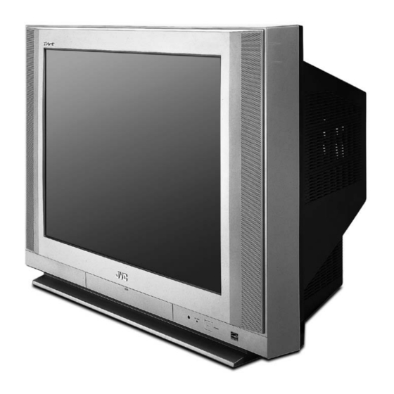
Related Manuals for JVC I'Art AV-32CF36


Summarization of Contents
PRECAUTIONS AND SAFETY CHECKS
SAFETY PRECAUTIONS
General safety precautions for service personnel, covering design, parts, and handling.
ISOLATION AND HIGH VOLTAGE CHECKS
Perform electrical safety checks like isolation and high voltage hold down circuit tests.
SPECIFIC SERVICE INSTRUCTIONS
HOW TO IDENTIFY MODELS
Guide on identifying models by appearance and rating label details.
TECHNICAL INFORMATION
MAIN MI-COM (CPU) PIN FUNCTION
Detailed list of Main MI-COM (CPU) pin names, I/O, and functions.
DISASSEMBLY PROCEDURE
DISASSEMBLY PROCEDURE
Step-by-step instructions for disassembling the TV unit and its components.
COMPONENT REMOVAL PROCEDURES
Procedures for removing specific components like rear cover, chassis, speakers, and PWBs.
CRT HANDLING PROCEDURES
CRT ANODE CAP INSULATION COATING
Procedure for applying silicon grease for electrical insulation on the CRT anode cap.
MEMORY IC REPLACEMENT AND SERVICE MODE
MEMORY IC REPLACEMENT PROCEDURE
Step-by-step procedure for replacing the memory IC.
SERVICE MODE SETTING ITEMS
List of adjustable items and their settings within the service mode.
FACTORY SHIPMENT SETTINGS
BUTTON AND REMOTE OPERATIONS
Factory shipment settings for button operations and remote control menu/direct operations.
CHIP COMPONENT REPLACEMENT
CAUTIONS AND REPLACEMENT STEPS
Cautions, soldering iron recommendations, and steps for replacing chip components.
ADJUSTMENT PROCEDURES
ADJUSTMENT PREPARATION AND ITEMS
Preparation, preset settings, instruments, and list of adjustment items.
ADJUSTMENT LOCATIONS
ADJUSTMENT LOCATIONS
Diagrams showing the locations of adjustment points on various PWB assemblies.
BASIC OPERATION OF SERVICE MODE
BASIC OPERATION OF SERVICE MODE
Overview of how to navigate and operate the TV's service mode.
SERVICE MODE OPERATIONS
ITEMS, ENTRY, STORAGE, AND EXIT
Details on service mode items, how to enter, store values, and exit.
SERVICE MODE SETTING DETAILS
V/C, DEF, SOUND, LOW/HIGH LIGHT
Details on adjusting V/C, DEF, Sound, Low Light, and High Light settings.
INITIAL SETTING VALUES OF SERVICE MODE
1.V/C(S) ADJUSTMENTS
Initial setting values for V/C(S) adjustments across different models (Pages 17-20).
2. DEF (D) ADJUSTMENTS
Initial setting values for Deflection (D) adjustments across different models.
3. SOUND(A) ADJUSTMENTS
Initial setting values for Sound (A) adjustments across different models.
4. OTHERS(F) SETTINGS
Initial setting values for factory settings (Others/F), marked as 'Do not adjust'.
5. 3L Y/C(LYC) SETTINGS
Initial setting values for 3L Y/C (LYC) separation control, marked as 'Do not adjust'.
12. SYSTEM(SYS) SETTINGS
Initial setting values for System (SYS) control circuit, marked as 'Do not adjust'.
ADJUSTMENT PROCEDURE
CHECK ITEM PROCEDURES
Procedures for checking B1 Voltage and High Voltage Hold Down circuit.
FOCUS AND DEFLECTION ADJUSTMENTS
Procedures for adjusting Focus, V. Size/Position, and H. Size/Position/Side Pin.
VIDEO CIRCUIT ADJUSTMENTS
Procedure for adjusting White Balance (Low Light) and Sub Bright/Contrast.
HIGH LIGHT, SUB BRIGHT, MTS ADJUSTMENTS
Adjustments for High Light, Sub Bright, Sub Contrast, and MTS Circuit levels/separation.
TROUBLESHOOTING
TROUBLESHOOTING INFORMATION
Indicates that troubleshooting information is not provided in this manual.
USING CIRCUIT DIAGRAMS
SAFETY AND NOTATIONS
Highlights safety-critical components and explains symbols/notations in circuit diagrams.
REPAIRING SERVICE NOTES
Important notes regarding GND differences and safety precautions during repair.
COMPONENT AND BOARD INFORMATION
USING P.W. BOARD
Table listing PWB assembly names and their corresponding part numbers for different models.
SEMICONDUCTOR SHAPES
Diagrams showing the bottom, front, and top views of transistors, ICs, and chip ICs.
BLOCK DIAGRAM
BLOCK DIAGRAM OVERVIEW
Overall block diagram illustrating the main functional sections and signal flow of the TV.
CIRCUIT DIAGRAMS
MAIN PWB CIRCUIT DIAGRAM
Detailed circuit diagram for the Main PWB, Sheet 1.
OTHER PWB CIRCUIT DIAGRAMS
Circuit diagrams for AV Selector, Front Control, and LED & Power Switch PWBs.
CRT SOCKET PWB CIRCUIT DIAGRAM
Circuit diagram for the CRT Socket PWB.
PATTERN DIAGRAMS
MAIN PWB PATTERN
Physical layout pattern diagram for the Main PWB.
OTHER PWB PATTERN DIAGRAMS
Physical layout pattern diagrams for AV Selector, Front Control, LED & Power, and CRT Socket PWBs.
PARTS LIST
CAUTION AND ABBREVIATIONS
Safety caution regarding parts and list of abbreviations for resistors and capacitors.
ASSEMBLY AND EXPLODED VIEWS
EXPLODED VIEW PARTS LISTS
Lists of parts for exploded view diagrams 1 and 2.
EXPLODED VIEW PARTS LIST -1
EXPLODED VIEW -1 DETAILS
Detailed parts list corresponding to the first exploded view illustration.
EXPLODED VIEW PARTS LIST -2
EXPLODED VIEW -2 DETAILS
Detailed parts list corresponding to the second exploded view illustration.
EXPLODED VIEW ILLUSTRATIONS
EXPLODED VIEW -2 ILLUSTRATION
Illustration showing the exploded view of internal components.
PRINTED WIRING BOARD PARTS LISTS
AV-27CF36/R MAIN P.W. BOARD
Parts list for the Main P.W. Board Assembly of model AV-27CF36/R.
AV-27CF36/R OTHER PWBs
Parts lists for Front Control and LED & Power SW P.W. Boards for AV-27CF36/R.
AV-27CF36/S MAIN P.W. BOARD
Parts list for the Main P.W. Board Assembly of model AV-27CF36/S.
AV-27CF36/S OTHER PWBs
Parts lists for CRT Socket, AV Selector, Front Control, and LED & Power SW PWBs.
AV-32CF36/Y MAIN P.W. BOARD
Parts list for the Main P.W. Board Assembly of model AV-32CF36/Y.
AV-32CF36/z MAIN P.W. BOARD
Parts list for the Main P.W. Board Assembly of model AV-32CF36/Z.
AV-32SF36/Y MAIN P.W. BOARD
Parts list for the Main P.W. Board Assembly of model AV-32SF36/Y.
AV-32SF36/z MAIN P.W. BOARD
Parts list for the Main P.W. Board Assembly of model AV-32SF36/Z.
AV-27SF36/s MAIN P.W. BOARD
Parts list for the Main P.W. Board Assembly of model AV-27SF36/S.
AV-27SF36/s OTHER PWBs
Parts lists for Front Control and LED & Power SW P.W. Boards for AV-27SF36/S.
AV-32SF36/Y MAIN P.W. BOARD
Parts list for the Main P.W. Board Assembly of model AV-32SF36/Y.
AV-32SF36/z MAIN P.W. BOARD
Parts list for the Main P.W. Board Assembly of model AV-32SF36/Z.
REMOTE CONTROL AND PACKING PARTS LISTS
REMOTE CONTROL UNIT PARTS LIST
Parts list for the Remote Control Unit RM-C203G-1C.
PACKING PARTS LIST
List of parts included in the product's packing.
Need help?
Do you have a question about the I'Art AV-32CF36 and is the answer not in the manual?
Questions and answers