Advertisement
Quick Links
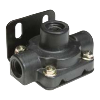
Bendix
®
QR-N
™
SPRING FOLLOWER
INSERT A
FIGURE 1
DESCRIPTION
The function of the Bendix
"speed up" the exhaust of air from the actuators it serves. It
is generally mounted on the vehicle axle midway between
the two actuators connected to it.
In the standard (Refer to Figure 1) QR-N
circular diaphragm is installed between the nonmetallic
upper body and stamped steel lower body. An o-ring seals
the two body halves which are held together using four 1/4"
machine screws and fl ange nuts.
In its standard confi guration the QR-N
with a 1 psi (6.9 kPa) maximum differential. For example
with supply pressure at 10 psi (68.9 kPa) delivery pressure
is 9 psi (61.8 kPa). Higher differential pressures are
available for special applications and are obtained by the
addition of a spring and diaphragm follower to the standard
™
QR-N
valve (Refer to Insert A).
Various pipe thread sizes are available for the single supply
port and two delivery ports of the QR-N
valve mounting is accomplished via two 11/32" diameter
holes on 1-1/2" centers.
Quick Release Valve
MOUNTING HOLE (2)
DELIVERY
PORT
CAP SCREW
DIFFERENTIAL SPRING
®
QR-N
™
quick release valve is to
™
valve a fl at
™
valve is supplied
™
valve. QR-N
SUPPLY PORT
EXHAUST PORT
OPERATION
With no air pressure applied to the QR-N
to Figure 1), the diaphragm is slightly fl exed by the upper
and lower body. In this condition the center portion of the
diaphragm rests on the exhaust port in the lower body while
the outer edge and opposite side of the diaphragm rests
against the sealing lip of the upper body.
APPLY
Air entering the supply port of the QR-N
center portion of the diaphragm to seal the exhaust port.
Simultaneously, the outer edge of the diaphragm moves
away from the sealing lip of the upper body allowing air to
fl ow from the supply port out the delivery ports.
BALANCE
When air pressure on both sides of the diaphragm
is approximately equal (1 psi differential), the natural
resiliency of the diaphragm material causes the outer
™
edge of the diaphragm to move into contact with the upper
body sealing lip. The QR-N
because air pressure bears against the center portion of
the diaphragm from one side only.
UPPER BODY
DIAPHRAGM
DELIVERY
LOCKWASHER
SEALING RING
™
valve (Refer
™
valve causes the
™
valve exhaust remains sealed
PORT
LOWER
BODY
1
Advertisement

Subscribe to Our Youtube Channel
Related Manuals for BENDIX QR-N QUICK RELEASE VALVE


Summary of Contents for BENDIX QR-N QUICK RELEASE VALVE
- Page 1 SEALING RING DIFFERENTIAL SPRING INSERT A FIGURE 1 DESCRIPTION OPERATION ™ The function of the Bendix ® QR-N ™ quick release valve is to With no air pressure applied to the QR-N valve (Refer “speed up” the exhaust of air from the actuators it serves. It to Figure 1), the diaphragm is slightly fl...
- Page 2 6. Never exceed manufacturer’s recommended PREVENTIVE MAINTENANCE pressures. Important: Review the Bendix Warranty Policy before 7. Never connect or disconnect a hose or line performing any intrusive maintenance procedures. A warranty may be voided if intrusive maintenance is containing pressure;...
- Page 3 (if applicable) in mineral spirits. Do using a genuine Bendix maintenance kit. not immerse nonmetallic components for a prolonged 5. Use only genuine Bendix replacement parts and period of time (no more than 10 minutes). Dry all parts components.
- Page 4 BW1586 © 2007 Bendix Commercial Vehicle Systems LLC All rights reserved. 9/2007 Printed in U.S.A.
Need help?
Do you have a question about the QR-N QUICK RELEASE VALVE and is the answer not in the manual?
Questions and answers