Table of Contents
Advertisement
Quick Links
®
®
™
Bendix
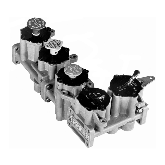
MV-1
Modutrol
5-3/8"
FIGURE 1 - MV-1
™
MODUTROL
DESCRIPTION
The Bendix
®
MV-1
™
modutrol assembly is an integrated air
control module designed for dash mounting in a truck/tractor.
The bodies for the modutrol assembly, as well as for the
"spool" inserts, are molded of a nonmetallic, noncorrosive
material. The assembly consists of three push-pull type
valves and two optional lever type valves. All valves utilize a
spool "insert," which can be replaced from the front of the
assembly without removal of the assembly or connecting
air lines.
The three push-pull type valves provide the following functions:
1. Tractor protection control.
VALVE A
VALVE B
VALVE C
VALVE D
2. Trailer service air supply.
3. System park.
4. Trailer park only.
5. Trailer recharge with tractor spring brakes applied.
Reference Figs. 1 & 5, valves V-1 and V-2 utilize identical
spool "inserts." The functions of valves V-1 and V-2 are
essentially the same as the Bendix
Valve V-3 utilizes a spool "insert" consisting of two valves; a
nonautomatic push-pull function similar to that of the Bendix
PP-8
™
valve, and a pilot operated three-way valve similar to
that of the Bendix
VALVE E
®
PP-1
®
™
SV-1
valve.
™
control valve.
®
1
Advertisement
Table of Contents

Subscribe to Our Youtube Channel
Related Manuals for BENDIX MV-1 MODUTROL


Summary of Contents for BENDIX MV-1 MODUTROL
- Page 1 Valve V-3 utilizes a spool “insert” consisting of two valves; a air lines. nonautomatic push-pull function similar to that of the Bendix ® PP-8 ™ valve, and a pilot operated three-way valve similar to The three push-pull type valves provide the following functions: ®...
- Page 2 The optional lever type valves housed in the auxiliary control The function as the lever type valves is similar to the Bendix ® ™ module consist of one or two lever type valves which may be TW-1 control valve. One or both of the valves may be utilized...
- Page 3 OPERATION OPERATING AND LEAKAGE TESTS The three push-pull control valves control all the required Prior to testing for leakage and function of the components functions of tractor spring brake control and trailer air in either module, the knobs must first be removed from the supply.
- Page 4 VALVE V-1 VALVE V-2 VALVE V-3 FIGURE 5 - PUSH-PULL VALVE LEAKAGE KEY AUXILIARY MODULE LEAKAGE CHART P-3 (SUPPLY) OPERATING MODE (SUPPLY CHARGED TO 100 PSI) VALVE POSITION Leakage Symptoms Correction Replace spool assy. in T-1 Replace spool assy. in T-2 Exhaust Hole P-7 Replace spool assy.
- Page 5 VALVE T-1 VALVE T-2 FIGURE 8 T-2 DELIVERY (P-3) SUPPLY T-1 DELIVERY SUPPLY (P-4) FIGURE 9...
- Page 6 10. Prior to returning the vehicle to service, make certain all components and systems are restored to their proper operating condition. BW1443 © 2004 Bendix Commercial Vehicle Systems LLC. All rights reserved. 3/2004 Printed in U.S.A.
Need help?
Do you have a question about the MV-1 MODUTROL and is the answer not in the manual?
Questions and answers