Table of Contents
Advertisement
Quick Links
Advertisement
Table of Contents

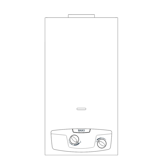
Summary of Contents for Baxi 14p
- Page 1 Baxi 11p Baxi 14p INSTALLATION, OPERATION AND MAINTENANCE MANUAL...
-
Page 3: General Safety
The device is well built in accordance with the current legislation. The CE sign positioned on the product indicates that it conforms to the following European Directives: 142/2009 93/68 0694 0694CP4791 WARNING This booklet contains information relevant to the user as well as the installer. The user must read the following chapters: General safety, Flue gas device and Operation. -
Page 4: General Safety Warnings
Two knobs to attach to the control panel after installation stance Centre ahead of time to save wasting time and money afterwards. Water filter to insert in the water valve pipe fitting. 1. TECHNICAL CHARACTERISTICS 1.a Technical Data Baxi 11p Baxi 14p kcal/h kcal/h Nominal power usage (Pn) 19,0 16.340... - Page 5 Misure in mm B (Ø) Fig. 1 Flue gas release safety device Release hood Heat exchanger Ignition electrode Burner Hydraulic valve Temperature regulator Gas valve Gas input Gas adjustment screws Piezoelectric button Gas control Devices pressure Ignition electrode Thermocouple Fig. 2...
-
Page 6: Installation
2.c Room ventilation 2. INSTALLATION The installation of the water heater must comply with regulations in 2.a Regulations force including any updates. See paragraph 2.a The use of gas devices is controlled by precise regulations. Warning: This device can only be installed in venues that are per- It is essential to observe regulations in force. -
Page 7: Water Connection
devices. The device ensures the correct release of combustion by- 2.e Water connection products; the flow of combustible gas to the release conduit and Connect the water heater to the water supply and insert a tap to in- the smoke channel. tercept the water above the device. - Page 8 spring guide disc is in its correct position (fig. 13) IV – ENABLING THE PRESSURE REGULATOR - Remount the diffuser attaching it to the upper hole - Remove the protective lid - Regulate the pressure screws so that the burner reaches the pressure levels indicated on the technical data on page 4 .
-
Page 9: Operation
Model 11p: for the extraction of 2.5 to 5.5 l/m the temperature of at the temperature necessary while saving gas. -
Page 10: Troubleshooting Problems And Solutions
- Remove the screws (C) - Shift the casing upwards to free it from the upper and lateral ho- - Shift the casing forwards - To reinsert the casing, follow the above steps in reverse order 4.b Troubleshooting: problems and solutions For the best functioning of the water heater, to prolong its lifetime and ensure that it is always safe, ensure that it is inspected at least once a year by a trained professional. -
Page 11: Serial Number Plate
IT-ES-PT: II2H3+ G20: 20 mbar Pn = Nominal power usage G30/G31: 28-30/37 mbar Qn = Nominal thermal range Baxi 11p Pm = Minimal power usage Qm = Minimal thermal range Pn = 19.0 O max = Maximum water pressure Qn = 21.8 Pm = 7.5...


Need help?
Do you have a question about the 14p and is the answer not in the manual?
Questions and answers