Chapters
Table of Contents

Related Manuals for Midea MV6-335WV2GN1


Summarization of Contents
Part 1: General Information
Indoor and Outdoor Unit Capacities
Details the capacity ranges for various indoor and outdoor units.
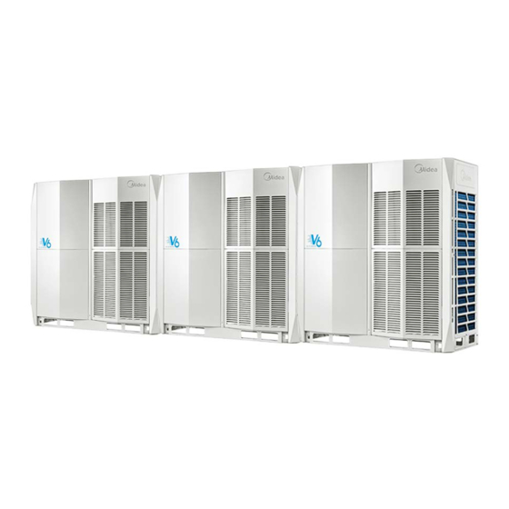
External Appearance
Illustrates the visual design and form factor of different indoor and outdoor units.
Outdoor Unit Combinations
Presents recommended configurations and pairings of outdoor units.
Combination Ratio
Outlines the limitations and rules for combining indoor and outdoor unit capacities.
Part 2: Components Layout and Refrigerant Circuits
Layout of Functional Components
Shows the internal arrangement of key components within the outdoor unit for different models.
Piping Diagrams
Displays the detailed refrigerant piping schematics for various unit capacities.
Refrigerant Flow Diagrams
Illustrates the path of refrigerant during different operational modes like cooling and heating.
Part 3: System Control
General Control Scheme Flowchart
Provides a high-level overview of the system's control logic and operational states.
Stop Operation
Explains the conditions and procedures that lead to the system stopping operation.
Standby Control
Details the control functions that manage the unit's state when it is in standby mode.
Startup Control
Describes the step-by-step process and component actions during system startup.
Normal Operation Control
Explains how components are managed during regular cooling and heating operations.
Protection Control
Outlines safety mechanisms and error handling to prevent system damage and ensure reliability.
Special Control
Covers specific operational modes like duty cycling and oil return procedures.
Part 4: Field Settings
Outdoor Unit Field Settings
Details the configuration options and switch settings for outdoor unit main PCBs.
Part 5: Electrical Components and Wiring Diagrams
Outdoor Unit Electric Control Box Layout
Shows the physical arrangement of electrical components within the outdoor unit's control box.
Outdoor Unit Main PCB
Describes the main printed circuit board, its ports, components, and their functions.
Wiring Diagrams
Provides comprehensive electrical wiring diagrams for different unit models.
Part 6: Diagnosis and Troubleshooting
Error Code Table
A comprehensive list of error codes, their meanings, and necessary actions for resolution.
Troubleshooting
Step-by-step guides and procedures for diagnosing and resolving system faults and errors.
Appendix to Part 6
Contains supplementary technical data, including sensor resistance characteristics.
Need help?
Do you have a question about the MV6-335WV2GN1 and is the answer not in the manual?
Questions and answers