Table of Contents
Advertisement
Quick Links
®
Bendix
ATR-1
®
™
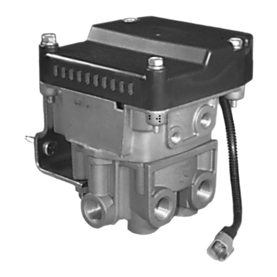
MOUNTING
BRACKET
BODY
SUPPLY
PORT
COVER PLATE FOR
REMOTE MOUNT
FIGURE 1 - ATR-1
ANTILOCK TRACTION RELAY VALVE
™
DESCRIPTION
The ATR-1
antilock traction relay is a specialized air brake
™
valve developed for use on Bendix antilock/traction equipped
vehicles.
It is essentially three separate valves working in combination
in a single housing. An R-14
valve and is fitted with a modified cover containing a double
check valve and a traction control solenoid. The ATR-1
contains both air and electric components to provide the
service braking and traction control (differential braking)
functions. A Bendix antilock traction controller can be
mounted to the ATR-1
™
valve or a cover plate can be installed
and the antilock controller mounted elsewhere on the vehicle.
When an ATR-1
valve is combined with an antilock traction
™
controller the resulting assembly is referred to as an antilock
traction assembly.
The ATR-1
valve replaces the standard relay valve used to
™
control the rear axle service brakes and performs the standard
relay function. Like the standard relay valve it replaces, the
ATR-1
valve (sometimes with attached antilock controller)
™
AntiLock Traction Relay Valve
CONTROLLER
MOUNTING HOLES (4)
SERVICE
REMOTE MOUNT ATR-1
style service relay is the base
™
TRACTION CONTROL
SOLENOID
UNDRILLED
"CON" PORT
PORT
RELAY VALVE
™
is normally mounted near the service brakes it serves. A
mounting bracket, furnished with the valve, permits either
frame or cross member mounting. All air connections on
the ATR-1
™
valve are identified for ease of installation. The
letter identification and air line connections are shown below
for reference.
ATR-1
VALVE AIR CONNECTION
™
valve
™
Supply (to reservoir)
Delivery (to brake Chamber)
Service (to brake valve rear delivery)
Control (not drilled or threaded on ATR-1
The ATR-1
™
which includes the R-12
The internal components of the relay portion of all of these
valves are interchangeable with the R-12
the same basic components are used to service all of them.
The ATR-1
™
to accommodate specific applications, however the standard
is 4 psi.
DELIVERY
PORT (4)
2 PIN SOLENOID
CONNECTOR
valve is part of the R-12
™
™
, R-14
™
, BP-R1
valve is available with various crack pressures
SUPPLY
PORT
EMBOSSED
IDENT.
SUP
DEL
SER
™
valve) CON
family of relay valves
™
, AR-1
™
.
valve and therefore
™
1
Advertisement
Table of Contents

Related Manuals for BENDIX ATR-1 ANTILOCK TRACTION RELAY


Summary of Contents for BENDIX ATR-1 ANTILOCK TRACTION RELAY
- Page 1 The ATR-1 antilock traction relay is a specialized air brake ™ frame or cross member mounting. All air connections on valve developed for use on Bendix antilock/traction equipped the ATR-1 ™ valve are identified for ease of installation. The vehicles.
-
Page 2: Operation
antilock components and their operation. For a description of antilock operation, refer to the appropriate Service Data Sheet covering the electronic controller used with the CONTROLLER ATR-1 valve. ™ SERVICE BRAKES APPLYING (FIGURE 4) Reservoir air pressure is present at the supply port and flows through internal body and cover passages to the supply of the normally closed (NC) traction control solenoid. - Page 3 CONTROLLER BRAKE VALVE TRACTION SOLENOID CHECK VALVE RELAY PISTON INLET EXHAUST MODULATOR REAR AXLE RESERVOIR SPRING BRAKE FIGURE 4 - SERVICE BRAKE APPLICATION SERVICE BRAKES HOLDING (FIGURE 5) its seat. The exhaust valve remains closed. With both the inlet and exhaust valves closed, air pressure in the brake The air pressure being delivered to the brake chambers is chambers is held stable and neither increases nor decreases.
- Page 4 CONTROLLER BRAKE TRACTION VALVE SOLENOID CHECK VALVE RELAY PISTON INLET EXHAUST MODULATOR REAR AXLE RESERVOIR SPRING BRAKE EXHAUST FIGURE 6 - SERVICE BRAKES RELEASING TRACTION CONTROL SERVICE APPLICATION SERVICE BRAKES RELEASING (FIGURE 6) (FIGURE 7) When the brake application is released, air from above the GENERAL relay piston flows back through the blend back and service pistons to the foot brake valve and is exhausted.
- Page 5 FIGURE 8 - PARTIAL ANTILOCK TRACTION SYSTEM SCHEMATIC...
-
Page 6: Preventive Maintenance
Never remove a component or plug unless you are certain all replaced with a new or genuine Bendix remanufactured unit, system pressure has been depleted. available at any authorized parts outlet. -
Page 7: Vehicle Preparation
Always check the vehicle brake or genuine Bendix remanufactured unit or repaired using system for proper operation after performing brake work and a genuine Bendix maintenance kit piece number 109368, before returning the vehicle to service. - Page 8 PRIOR INTERNAL COMPONENT CONFIGURATION Assembly of items 29-35 Key Description Key Description ECU Control 19 Relay Piston Bolts (4) 20 Piston Spring (if used) Cover 21 O-Ring Base 22 Retaining Ring Retaining Ring 23 Check Valve* Exhaust Cover 24 O-Ring O-Ring 25 Inlet Seat* O-Ring...
-
Page 9: Cleaning And Inspection
DISASSEMBLY Then, depending on the internal configuration: 12a. Remove check valve seat(23), with o-rings(27 & 28). PREPARATION FOR DISASSEMBLY Remove o-rings(27 & 28) from the check valve seat. 1. Remove all air fittings and plugs from the valve. Then Remove the check valve(24), guide(25), and 2. - Page 10 ASSEMBLY 1. Prior to assembly, lubricate all o-rings, seals, and pistons, 4b. Install the o-ring(34) onto the plug(35). Install into the cover(3) bore and while holding it in place install the as well as body and cover bores, using silicone lubricant. retaining ring(22).
- Page 11 NOTES...
- Page 12 BW1794 © 2004 Bendix Commercial Vehicle Systems LLC 10/2004 Printed in U.S.A. All rights reserved.
Need help?
Do you have a question about the ATR-1 ANTILOCK TRACTION RELAY and is the answer not in the manual?
Questions and answers