Table of Contents
Advertisement
Quick Links
ALL phases of this installation must comply with NATIONAL, STATE AND LOCAL CODES
IMPORTANT - This Document is customer property and is to remain with this unit. Please return to service informa-
tion pack upon completion of work.
These instructions do not cover all variations in systems or provide for every possible contingency to be met in connection with
the installation. Should further information be desired or should particular problems arise which are not covered sufficiently for the
purchaser's purposes, the matter should be referred to your installing dealer or local distributor.
Note: The manufacturer recommends installing only approved matched indoor and outdoor systems. Some of the benefits of
installing approved matched indoor and outdoor split systems are maximum efficiency, optimum performance and the best overall
system reliability.
Table of Contents
Section 1. Safety ..................................................................................... 2
Section 2. Unit Location Considerations ............................................. 3
Section 3. Unit Preparation .................................................................... 5
Section 4. Setting the Unit ..................................................................... 5
Section 5. Refrigerant Line Considerations ......................................... 6
Section 6. Refrigerant Line Routing ..................................................... 8
Section 7. Refrigerant Line Brazing ...................................................... 9
Section 8. Refrigerant Line Leak Check ............................................. 11
Section 9. Evacuation .......................................................................... 12
Section 10. Service Valves .................................................................. 12
Section 11. Electrical - Low Voltage ................................................... 13
Section 12. Electrical - High Voltage .................................................. 15
Section 13. Start Up .............................................................................. 16
Section 14. System Charge Adjustment ............................................. 17
Section 15. Checkout Procedures ...................................................... 23
Section 16. Refrigerant Circuits .......................................................... 24
Section 17. Wiring Diagrams ............................................................... 26
Section 18. Pressure Curves ............................................................... 34
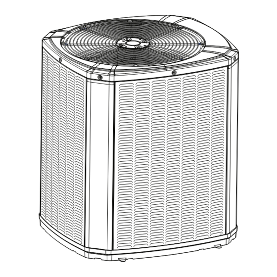
Installation and Operation Manual
Condensing Units
4TTR3
18-AC79D1-10D-EN
Advertisement
Table of Contents

Related Manuals for Trane 4TTR3042E


Summarization of Contents
Section 2. Unit Location Considerations
2.1 Unit Dimensions and Weight
Details unit dimensions and weight specifications for various models.
2.2 Refrigerant Piping Limits
Specifies maximum total and vertical refrigerant line lengths.
2.3 Suggested Locations for Best Reliability
Provides guidance on optimal unit placement for airflow and noise reduction.
2.4 Cold Climate Considerations
Offers precautions for units in areas prone to snow and freezing temperatures.
Section 3. Unit Preparation
3.1 Prepare The Unit For Installation
Steps for preparing the unit before installation, including damage checks.
Section 4. Setting the Unit
4.1 Pad Installation
Guidelines for installing the unit on a suitable support pad.
Section 5. Refrigerant Line Considerations
5.1 Refrigerant Line and Service Valve Connection Sizes
Table detailing line sizes and connection sizes for various models.
5.2 Factory Charge
Information on factory refrigerant charge and verification.
5.3 Required Refrigerant Line Length
Prompts for measuring line length and lift for system charging.
5.4 Refrigerant Line Insulation
Importance of insulating the vapor line and preventing metal contact.
Section 6. Refrigerant Line Routing
6.1 Precautions
Guidelines for routing refrigerant lines to prevent noise and ensure proper installation.
Section 7. Refrigerant Line Brazing
7.1 Braze The Refrigerant Lines
Step-by-step instructions for brazing refrigerant lines.
Section 8. Refrigerant Line Leak Check
8.1 Check For Leaks
Procedure for pressurizing lines and checking for leaks with soapy solution.
Section 9. Evacuation
9.1 Evacuate the Refrigerant Lines and Indoor Coil
Steps for evacuating the system to the required vacuum level.
Section 10. Service Valves
10.1 Open the Gas Service Valve
Instructions for opening the gas service valve after leak check and evacuation.
10.1 Open the Liquid Service Valve
Procedure for carefully opening the liquid line service valve.
Section 11. Electrical - Low Voltage
11.1 Low Voltage Maximum Wire Length
Table defining maximum low voltage wire lengths based on gauge.
11.2 Low Voltage Hook-up Diagrams
Wiring diagrams for connecting thermostat, air handler, and outdoor unit.
Section 12. Electrical - High Voltage
12.1 High Voltage Power Supply
Safety warnings and requirements for high voltage power supply.
12.2 High Voltage Disconnect Switch
Recommendation to install a separate disconnect switch for high voltage.
12.3 High Voltage Ground
Requirement for proper grounding of the outdoor unit.
Section 13. Start Up
13.1 System Start Up
Step-by-step procedure for starting the system after installation.
Section 14. System Charge Adjustment
14.1 Temperature Measurements
Instructions for measuring outdoor and indoor temperatures for charging.
14.2 Subcooling Charging in Cooling (Above 55° F Outdoor Temp.)
Method for charging based on subcooling above 55°F outdoor temperature.
14.3 Subcooling Charging Below 55° F Outdoor Temp.
Method for charging below 55°F outdoor temperature using weighing.
Section 15. Checkout Procedures
15.1 Operational And Checkout Procedures
Final checks and procedures for unit operation and performance.
Need help?
Do you have a question about the 4TTR3042E and is the answer not in the manual?
Questions and answers