Table of Contents
Advertisement
Quick Links
SERVICE
A3 Mono Copier
Refer to the service manual in the GSPN (see the rear cover) for more information.
A3 Mono Copier
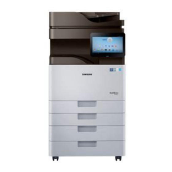
MultiXpress K7 series
SL-K7600GX / K7500GX /
K7400GX, SL-K7600LX / K7500LX
/ K7400LX
(Ver 1.12)
MANUAL
1. Precautions
2. Product Specifications and Description
3. Disassembly and Reassembly
4. Troubleshooting
5. Connection Diagram
6. Reference Information
Contents
Advertisement
Table of Contents
Troubleshooting

Summarization of Contents
Precautions
Safety Warning
Critical safety instructions for servicing and using the product.
Caution for Safety
Precautions regarding toxic materials and electrical shock hazards.
Handling Precautions
Guidelines for safe personal handling and product care.
Assembly and Disassembly Precautions
Procedures and warnings for safe parts replacement and assembly.
Bodily Injury Warnings
Warnings about high temperatures, rotating parts, and lifting techniques.
ESD Precautions
Guidelines for handling electrostatic discharge sensitive components.
Product Specifications and Description
Product Overview
General overview of the copier's key features like printing speed and LCD.
General Specifications
Detailed specifications including processor, memory, storage, and interface details.
Print Specifications
Details on printing speed, FPOT, resolution, printer languages, and OS support.
Scan Specifications
Details on scan speed, compatibility, file formats, resolution, and destinations.
Copy Specifications
Specifications for copying speed, resolution, reduce/enlarge options, and controls.
Fax Specifications
Details on fax compatibility, modem speed, scan speed, resolution, and features.
Paper Handling Specifications
Information on input capacity, standard cassette tray, multipurpose tray, and media types.
Network and Software Specifications
Details on network interface, protocols, IP addressing, MIB access, and software solutions.
Supplies
Information on toner cartridge, OPC drum unit, and waste toner container yields.
Maintenance Parts
List of maintenance parts with part codes, life, and remarks, including a maintenance table.
Options
Configuration and list of available optional units like job separators and finishers.
Disassembly and Reassembly
Precautions for Part Replacement
Safety guidelines for assembling, disassembling, and handling PBAs.
Machine Cleaning for Maintenance
Procedures for cleaning the scan glass and DSDF white bar.
Cleaning the Paper Dust Stick
Step-by-step instructions for cleaning the paper dust stick.
Development (Deve) Unit Replacement
Detailed instructions for replacing the development unit.
Fuser Unit Replacement
Step-by-step guide for replacing the fuser unit, including safety cautions.
Paper Transfer Belt Replacement
Instructions for removing and replacing the Paper Transfer Belt (PTB) Assy.
Pick-Up, Separation, Forward Roller Replacement
Procedure for replacing pick-up, reverse, and forward rollers.
DSDF Pick-up Roller Assy (LX Model) Replacement
Instructions for removing and replacing the DSDF pick-up roller assembly.
DSDF Reverse Roller (LX Model) Replacement
Procedure for removing and replacing the DSDF reverse roller.
DSDF Pick-up Roller Assy (GX Model) Replacement
Instructions for removing and replacing the DSDF pick-up roller assembly for GX models.
DSDF Reverse Roller Assy (GX Model) Replacement
Procedure for removing and replacing the DSDF reverse roller assembly for GX models.
Left Cover Removal
Steps to remove the left cover of the machine.
Rear Cover Removal
Instructions for removing the rear cover of the machine.
LSU Removal
Procedure for removing the Laser Scanning Unit (LSU).
Temperature/Humidity Sensor Replacement
Steps to remove and replace the temperature and humidity sensor.
Reservoir Assy Replacement
Procedure for removing the reservoir assembly.
OPE Unit Removal
Instructions for removing the Operator Panel Equipment (OPE) unit.
Main Board Replacement
Steps to remove and replace the main controller board.
HVPS Board Replacement
Procedure for removing and replacing the High Voltage Power Supply (HVPS) board.
SMPS Board Replacement
Instructions for replacing SMPS boards (board 1, 2, and 3).
Fuser Drive Board (FDB) Replacement
Steps to remove and replace the Fuser Drive Board (FDB).
Troubleshooting
Control Panel Troubleshooting
Guidance on using the control panel, display screen, and buttons.
Understanding Status LEDs
Explanation of machine status indicated by LED colors and patterns.
Updating Firmware
Instructions for updating printer firmware via control panel or network.
JAM Removal Procedures
Steps to clear various types of paper jams (original, tray, exit).
Entering Service Mode (Tech Mode)
Instructions on how to access and navigate the service mode.
Diagnostics
Procedures for engine, fax, and scanner diagnostics, including adjustments.
Service Functions
Access to functions like memory clear, hard disk maintenance, and network port settings.
Error Code Troubleshooting
A comprehensive list of error codes and their troubleshooting steps.
Image Quality Problems and Solutions
Analysis and solutions for common print quality defects like lines, blur, and poor fusing.
Feeding System Problems
Troubleshooting issues with paper pickup, feeding, and wrinkling.
Electrical Circuit Problems
Troubleshooting common electrical issues like SMPS voltage drop and network errors.
Adjustment Procedures
Guides for adjusting ADF skew, scan FR carriage flatness, and scan top skew.
SPDS Application Guide
Information on using the SPDS application for diagnostics and troubleshooting.
Connection Diagrams
Connection Diagram: Fuser, Exit, Duplex, Toner
Wiring diagram for the fuser, exit, duplex, and toner components.
Connection Diagram: Scanner
Wiring diagram for the scanner unit, including DSDF and CCDM connections.
Connection Diagram: LSU, OPE, USB
Wiring diagram for the Laser Scanning Unit, Operator Panel, and USB connections.
Connection Diagram: Side, MP, Feed, Regi, Pick-Up
Wiring diagram for side unit, MP tray, feed, regi, and pick-up components.
Connection Diagram: OPC, WTB, CST Lock
Wiring diagram for OPC drum, Waste Toner Bottle, and CST Lock components.
Connection Diagram: HVPS, SMPS, FDB
Wiring diagram for High Voltage Power Supply, SMPS, and Fuser Drive Board.
Reference Information
Tools for Troubleshooting
List of recommended tools for performing troubleshooting and maintenance.
Glossary of Terms
Definitions of technical terms used throughout the manual.
Model Name and Code Information
Explanation of the model naming conventions and codes used.
Document Revision List
Record of changes and updates made to the service manual.


Need help?
Do you have a question about the SL-K7500GX and is the answer not in the manual?
Questions and answers