Advertisement
Service Literature
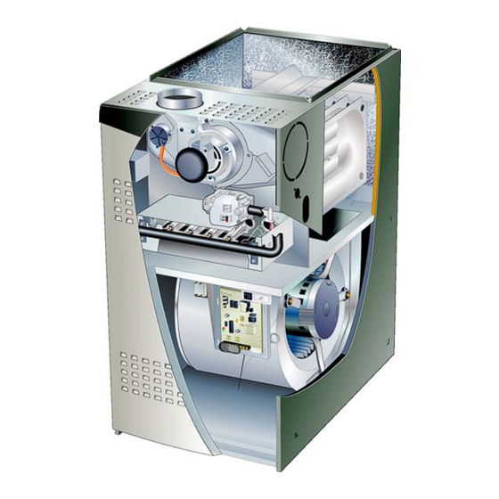
EL180UHE(X) series units are mid-efficiency gas furnaces
used for upflow or horizontal applications only, manufac
tured with Lennox Duralokt heat exchangers formed of
aluminized steel. EL180UHE(X) units are available in heat
ing capacities of 44,000 to 132,000 Btuh and cooling ap
plications 2 to 5 tons. Refer to Engineering Handbook for
proper sizing.
Units are factory equipped for use with natural gas. Kits are
available for conversion to LP/Propane operation.
EL180UHE(X) model units are equipped with a hot surface
ignition system. The EL180UHE(X) unit meets the Califor
nia Nitrogen Oxides (NO
) Standards and California Sea
x
sonal Efficiency requirements. All units use a redundant
gas valve to assure safety shut-off as required by C.S.A.
All specifications in this manual are subject to change. Pro
cedures outlined in this manual are presented as a recom
mendation only and do not supersede or replace local or
state codes. In the absence of local or state codes, the
guidelines and procedures outlined in this manual (except
where noted) are recommended only and do not constitute
code.
TABLE OF CONTENTS
. . . . . . . . . . . . . . . . . . . . . . . . . . . . .
. . . . . . . . . . . . . . . . . . . . . . . . . . . . . .
. . . . . . . . . . . . . . . . . . . . . . . . .
. . . . . . . . . . . . . . . . . . . . . . . .
II Installation
. . . . . . . . . . . . . . . . . . . . . . . . . . . . .
. . . . . . . . . . . . . . . . . . . . . . . . . . . . . .
. . . . . . . . . . . . . . . . . . . . . . . . . .
Corp. 1302-L1
Revised 06-2013
Page 2
Page 4
Page 6
Page 7
Page 20
Page 20
. . . . . . . . .
Page 20
. . . . . . . . .
Page 25
Page 25
. . . . . .
Page 28
Page 1
EL180UHE(X)
WARNING
Improper installation, adjustment, alteration, service
or maintenance can cause property damage, person
al injury or loss of life. Installation and service must
be performed by a licensed professional HVAC in
staller (or equivalent), service agency or the gas sup
plier.
WARNING
Electric shock hazard. Can cause injury
or death. Before attempting to perform
any service or maintenance, turn the
electrical power to unit OFF at discon
nect switch(es). Unit may have multiple
power supplies.
WARNING
Sharp edges.
Be careful when servicing unit to avoid sharp edges
which may result in personal injury.
© 2013 Lennox Industries Inc.
Advertisement
Table of Contents

Related Manuals for Lennox EL180UH070E36B


Summarization of Contents
SPECIFICATIONS
Gas Heating and Installation Data
Covers AFUE, input/output, temp rise, clearances, and pipe sizes for different models.
Electrical, Shipping, and Blower Data
Details electrical specs, shipping weight, and blower performance parameters.
Optional Accessories and High Altitude Adjustments
Cabinet, Filter, and Gas Heat Accessories
Lists optional kits, filter sizes, and gas heat accessories for various models.
High Altitude Derating Guidelines
Explains derating for altitudes above 2000 ft and provides related pressure data.
Blower Performance Data
EL180UH045E36A and EL180UH070E36B Performance
Blower performance (cfm/watts) at various static pressures and speeds for two models.
EL180UH090E48B Performance
Blower performance (cfm/watts) at various static pressures and speeds for a specific model.
Blower Performance Data
EL180UH090E60C and EL180UH110E60C Performance
Blower performance (cfm/watts) for specific models at various static pressures and speeds.
EL180UH135E60D Performance
Blower performance (cfm/watts) for a specific model at various static pressures and speeds.
Unit Component Descriptions
Control Transformer, Interlock, and Breaker
Explains the function of the transformer, door interlock switch, and circuit breaker.
Integrated Control and Electronic Ignition
Details the integrated control, its features, and the electronic ignition sequence.
Fan Operation and Timing Controls
Heating Fan Timing Adjustments
Information on adjustable and non-adjustable heating fan on/off times.
Cooling Fan Timing Specifications
Details non-adjustable cooling fan on/off times and their factory settings.
Furnace Component Details
Rollout, Primary Limit, and Flame Sensor
Explains the function and safety aspects of rollout switches, primary limit control, and flame sensor.
Measuring Flame Signal
Flame Signal Microamp Readings
Provides a table of normal, low, and dropout microamp readings for flame signal.
Furnace Component Functions
Gas Valve and Combustion Air Inducer Operation
Details the gas valve, its redundancy, and the function of the combustion air inducer.
Ignitor Checks and Specifications
Outlines ignitor material, resistance, voltage, and basic troubleshooting checks.
Ignitor Troubleshooting Procedures
Ignitor Resistance and Voltage Testing
Detailed steps for testing ignitor resistance and voltage supply.
Combustion Air Inducer Pressure Switch
Pressure Switch Function and Testing
Explains the pressure switch role in safety and provides troubleshooting guidance.
Furnace Venting and Installation Notes
Multiple Venting Positions and Requirements
Describes furnace venting configurations and installation considerations.
Blower Motor Service and Replacement
Blower Wheel Alignment and Motor Testing
Instructions for blower wheel centering, motor set screw alignment, and initial motor tests.
Motor Control Module Installation
Guidelines for installing a replacement motor control module, including torque and drip loop.
Blower Motor Electrical Troubleshooting
Power, Fan Speed, and Control Voltage Tests
Detailed tests for blower motor power, fan speed signals, and control voltages.
Motor Module Replacement and Testing
Harness Disconnection and Motor Resistance Tests
Steps for unplugging harnesses, testing motor resistance, and checking continuity.
Motor Control Module Installation and Drip Loop
Guidelines for installing a new motor control module, including torque and drip loop formation.
Installation, Start-Up, and Safety Procedures
Unit Installation, Heating Start-Up, and Shutdown
Covers unit installation, heating start-up, safety, and shutdown protocols.
Heating System Service Checks and Gas Piping
Details CSA certification, gas piping requirements, and leak testing procedures.
Gas Pressure, Flow, and Combustion Analysis
Gas Pressure Adjustment and Supply Measurement
Procedures for adjusting gas pressure, measuring supply pressure, and checking flow.
Proper Combustion and High Altitude Settings
Guidelines for checking combustion efficiency, CO levels, and high altitude adjustments.
Ground and Voltage Verification Procedures
Line Voltage Checks for Grounding
Procedures to measure AC voltage for proper grounding and voltage levels.
Typical Operating Characteristics
Blower Operation, Speed, and Static Pressure
Covers blower operation, speed tap adjustment, and external static pressure measurement.
Temperature Rise and Fan Timing
Explains temperature rise dependence and fan timing controls.
Maintenance and Cleaning Procedures
Preliminary Checks and Filter Maintenance
Covers initial checks, electrical inspection, and filter upkeep.
Heat Exchanger and Burner Cleaning
Detailed steps for cleaning the heat exchanger and burners.
Component Removal and Reassembly
Burner, Inducer, and Heat Exchanger Service
Instructions for removing and reinstalling the burner assembly, inducer, and heat exchanger.
System Checks and Maintenance
Supply Air Blower and Flue System Inspection
Covers blower wheel cleaning and inspection of the flue and chimney system.
Electrical System and Amp Draw Checks
Procedures for checking electrical wiring, voltage, and motor amp draw.
Wiring and Sequence of Operation
EL180UHE Schematic and Heating Sequence
Provides the wiring diagram and a detailed sequence of operation for heating.
Heating Sequence Troubleshooting Guide
Initial System Checks and Fault Codes
Verifies control self-check, polarity, ground, voltage, and component states for troubleshooting.
Burner, Limit, and Pressure Switch Verification
Checks burner operation, flame presence, primary limit, and pressure switch status for faults.
Continued Heating Sequence Troubleshooting
Ignitor, Flame Sensing, and Limit Checks
Monitors ignitor performance, flame signal, and limit/pressure switch operations.
Rollout, Pressure Switch Faults, and Watchguard
Analyzes fault codes for rollout, pressure switches, and watchguard conditions.
Cooling Sequence Troubleshooting Flow
Cooling Control, Ground, Polarity, and Voltage Checks
Verifies control operation, ground, polarity, and voltage in cooling mode.
Rollout Switch and Cooling Call Monitoring
Monitors rollout switch status and response to thermostat calls for cooling.
Continuous Fan Sequence Troubleshooting
Fan Operation During Heat and Cool Calls
Describes fan behavior during manual selection and heating/cooling demands.
Need help?
Do you have a question about the EL180UH070E36B and is the answer not in the manual?
Questions and answers