Lennox EL180UHE Series Manual
Hide thumbs
Also See for EL180UHE Series:
- Installation instructions manual (32 pages) ,
- Installation instructions manual (34 pages)
Advertisement
Service Literature
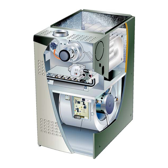
EL180UHE(X) series units are mid-efficiency gas furnaces
used for upflow or horizontal applications only, manufac
tured with Lennox Duralokt heat exchangers formed of
aluminized steel. EL180UHE(X) units are available in heat
ing capacities of 44,000 to 132,000 Btuh and cooling ap
plications 2 to 5 tons. Refer to Engineering Handbook for
proper sizing.
Units are factory equipped for use with natural gas. Kits are
available for conversion to LP/Propane operation.
EL180UHE(X) model units are equipped with a hot surface
ignition system. The EL180UHE(X) unit meets the Califor
nia Nitrogen Oxides (NO
) Standards and California Sea
x
sonal Efficiency requirements. All units use a redundant
gas valve to assure safety shut-off as required by C.S.A.
All specifications in this manual are subject to change. Pro
cedures outlined in this manual are presented as a recom
mendation only and do not supersede or replace local or
state codes. In the absence of local or state codes, the
guidelines and procedures outlined in this manual (except
where noted) are recommended only and do not constitute
code.
TABLE OF CONTENTS
. . . . . . . . . . . . . . . . . . . . . . . . . . . . .
. . . . . . . . . . . . . . . . . . . . . . . . . . . . . .
. . . . . . . . . . . . . . . . . . . . . . . . .
. . . . . . . . . . . . . . . . . . . . . . . .
II Installation
. . . . . . . . . . . . . . . . . . . . . . . . . . . . .
. . . . . . . . . . . . . . . . . . . . . . . . . . . . . .
. . . . . . . . . . . . . . . . . . . . . . . . . .
Corp. 1302-L1
Revised 06-2013
Page 2
Page 4
Page 6
Page 7
Page 20
Page 20
. . . . . . . . .
Page 20
. . . . . . . . .
Page 25
Page 25
. . . . . .
Page 28
Page 1
EL180UHE(X)
WARNING
Improper installation, adjustment, alteration, service
or maintenance can cause property damage, person
al injury or loss of life. Installation and service must
be performed by a licensed professional HVAC in
staller (or equivalent), service agency or the gas sup
plier.
WARNING
Electric shock hazard. Can cause injury
or death. Before attempting to perform
any service or maintenance, turn the
electrical power to unit OFF at discon
nect switch(es). Unit may have multiple
power supplies.
WARNING
Sharp edges.
Be careful when servicing unit to avoid sharp edges
which may result in personal injury.
© 2013 Lennox Industries Inc.
Advertisement
Table of Contents


Need help?
Do you have a question about the EL180UHE Series and is the answer not in the manual?
Questions and answers