Table of Contents
Advertisement
Bedienungsanleitung
Operation Manual
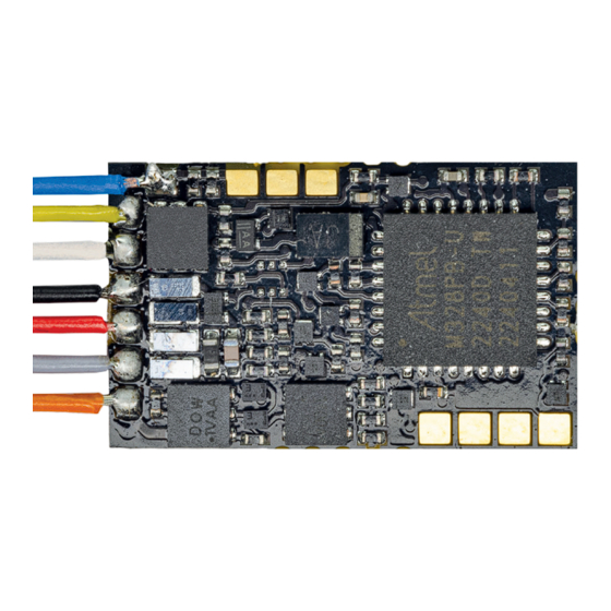
N Lokdecoder
5296 mit Kabel
5297 mit Stiftleiste 6 polig NEM 651 S
5298 mit Next18
N Locomotive decoder
5296 with cable
5297 with 6-pole plug connector to NEM 651 S
5298 with Next18
1. Wichtige Hinweise / Important information ........................................................ 2
2. Einleitung / Introduction ..................................................................................... 3
3. Einbau und Anschluss / Mounting and Connection ........................................... 7
4. Programmierung / Programming ....................................................................... 10
5. Konfigurationsvariablen (CV) / Configuration variables (CV) ............................ 14
6. Betrieb / Operation ............................................................................................ 19
7. Fehlersuche und Abhilfe / Trouble-shooting ...................................................... 21
8. Gewährleistung / Warranty ................................................................................ 22
9. Technische Daten / Technical data .................................................................... 23
Lokadresse:
Locomotive address:
Eingebaut in Lok:
Mounted in locomotive:
DC
DCC
MM
=
Rail
Com
SuSi
Innovation,
die bewegt!
Advertisement
Table of Contents

Related Manuals for Viessmann 5297


Summarization of Contents
1. Important Information
1.1 Safety Instructions
Essential safety precautions and warnings for handling the decoder and its components during installation and operation.
1.2 Correct Product Use
Outlines the intended applications and operational environment for the locomotive decoder to ensure proper usage.
1.3 Package Contents Check
Lists all items included in the decoder package to verify completeness before proceeding with installation.
2. Functions
2.1 Digital Operation Modes
Explains decoder operation in DCC and Motorola digital environments, including automatic format recognition.
2.2 Analogue Mode Operation
Details the decoder's functionality and automatic detection for operation on analogue DC model railway layouts.
2.3 Overload Protection
Describes the integrated protection mechanism that safeguards the decoder from excessive current draw on function outputs.
2.4 Motor Control
Covers the decoder's motor control using PWM for smooth and quiet operation, suitable for various motor types.
2.5 Load Control
Explains how load control maintains constant locomotive speed regardless of load, detailing adjustable parameters.
2.6 Speed Curve Adjustment
Details the adjustment of locomotive speed characteristics for achieving realistic driving behavior.
Freeform Speed Curve Setup
Method to create a custom speed curve by defining values for each speed step using a table (CVs 67-94).
Linear Speed Curve Setup
Method to automatically generate a linear speed curve by setting start, middle, and maximum speeds (CVs 2, 5, 6).
2.7 Shunting Mode
Describes the shunting mode that disables acceleration and braking delays for precise low-speed locomotive control.
2.8 Acceleration and Brake Rates
Explains how acceleration and braking delays can be individually programmed for smooth speed transition.
2.9 Function and Lighting Outputs
Details the two function outputs for controlling lights, sound, or other accessories, including function mapping.
2.10 Function Output Effects
Covers programmable effects for function outputs like dimming, blinking, and uncoupling operations.
2.11 SUSI Interface
Explains the connection and programming of SUSI modules for enhanced locomotive functionality, such as sound effects.
2.12 RailCom Feedback
Describes the RailCom protocol for bidirectional communication and data feedback from the decoder to the command station.
3. Mounting and Connection
3.1 NEM 651 Interface Installation
Step-by-step guide for installing the decoder into locomotives equipped with a standard NEM 651 interface socket.
3.2 Wire Harness Installation
Instructions for installing the decoder with wire harness in locomotives lacking a standard interface socket.
3.3 Next18 Socket Installation
Guide for installing the decoder into locomotives featuring a Next18 interface socket for connection.
3.4 Connecting Accessories to Outputs
Procedures for connecting accessories like lights to the decoder's function outputs, considering current limits.
3.5 Factory Default Settings
Outlines the default assignments for function outputs, shunting mode, and other settings at the factory.
3.6 Connecting LEDs
Details how to connect LEDs to the decoder's function outputs, including requirements for series resistors.
3.7 Connecting SUSI Modules
Explains the specific soldering points for attaching a SUSI module to the decoder for extended features.
3.8 Buffer Capacitor Connection
Information on connecting a buffer capacitor to improve power supply stability on tracks with poor electrical contact.
3.9 Decoder Installation
Advice on securely mounting the decoder within the locomotive, especially if no specific compartment is available.
4. Programming
4.1 DCC Command Station Programming
Instructions for programming decoder configuration variables (CVs) using a DCC command station.
4.2 Motorola Central Unit Programming
Guide for programming the decoder using Motorola protocol command stations, including register settings.
4.3 Motorola Extended Mode Programming Tip
Provides a tip for utilizing the extended Motorola programming mode for advanced configuration values.
6. Operation
6.1 Optimizing CV Settings
Guide for fine-tuning CV settings, particularly load control parameters, for optimal locomotive performance and smooth running.
6.2 RailCom Operation
Explains how to operate and read data using the RailCom protocol, requiring specific DCC system features for communication.
Need help?
Do you have a question about the 5297 and is the answer not in the manual?
Questions and answers