Table of Contents
Advertisement
Bedienungsanleitung
Operation Manual
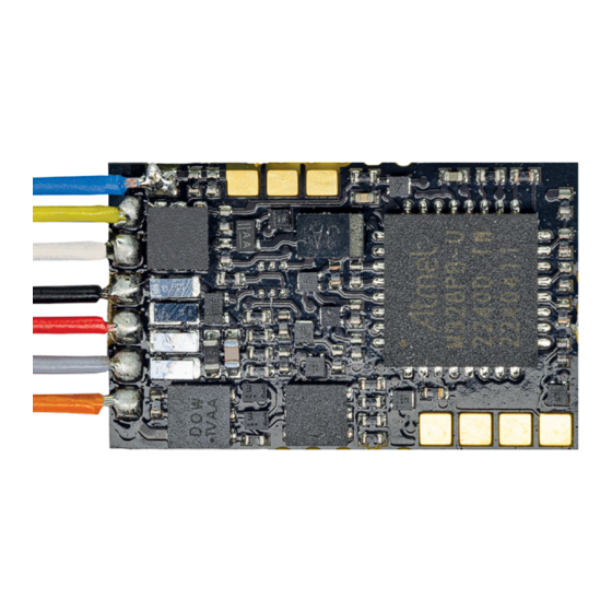
N Lokdecoder
5296 mit Kabel
5297 mit Stiftleiste 6 polig NEM 651 S
5298 mit Next18
N Locomotive decoder
5296 with cable
5297 with 6-pole plug connector to NEM 651 S
5298 with Next18
1. Wichtige Hinweise / Important information ........................................................ 2
2. Einleitung / Introduction ..................................................................................... 3
3. Einbau und Anschluss / Mounting and Connection ........................................... 7
4. Programmierung / Programming ....................................................................... 10
5. Konfigurationsvariablen (CV) / Configuration variables (CV) ............................ 14
6. Betrieb / Operation ............................................................................................ 19
7. Fehlersuche und Abhilfe / Trouble-shooting ...................................................... 21
8. Gewährleistung / Warranty ................................................................................ 22
9. Technische Daten / Technical data .................................................................... 23
Lokadresse:
Locomotive address:
Eingebaut in Lok:
Mounted in locomotive:
DC
DCC
MM
=
Rail
Com
SuSi
Innovation,
die bewegt!
Advertisement
Table of Contents

Subscribe to Our Youtube Channel
Related Manuals for Viessmann 5296


Summary of Contents for Viessmann 5296
-
Page 1: Table Of Contents
Bedienungsanleitung Operation Manual N Lokdecoder 5296 mit Kabel 5297 mit Stiftleiste 6 polig NEM 651 S 5298 mit Next18 N Locomotive decoder 5296 with cable Lokadresse: 5297 with 6-pole plug connector to NEM 651 S Locomotive address: 5298 with Next18... -
Page 2: Wichtige Hinweise / Important Information
Check the contents of the package for complete- digkeit: ness: - N Decoder 5296 mit Anschlusskabel oder - N decoder 5296 with cable or - N Decoder 5297 mit Stiftleiste 6 polig NEM 651 S - N decoder 5297 with 6-pole plug connector to... -
Page 3: Einleitung / Introduction
2. Funktionen 2. Functions Programmierung der Funktionen: Programming the functions: Die Funktionen des Decoders richten Sie über die Please program the functions of the decoder by CV-Programmierung ein. Sämtliche Einstellmöglich- means of the CV programming. You find all pos- keiten finden Sie in Kapitel 5. sible options in chapter 5. - Page 4 Überlast nicht gelingt, wird dies in immer größeren Ab- be repeated in increased intervals. As soon as the ständen wiederholt. Ist die Überlast beseitigt, werden overload is cleared, the outputs will be switched on die Ausgänge normal eingeschaltet. regularly. Vorsicht: Caution: Bei einem Kurzschluss an den Motorausgängen In case of a short circuit between the motor out- gegen das Lokchassis werden die Motorausgän- puts and the chassis the motor outputs will be ge abgeschaltet.
- Page 5 Fahren nach Tabelle: In den CVs 67 bis 94 kann Freeform speed curve: The values in CV 67 to 94 eine freie Kennlinie in Form einer Fahrstufentabelle define a freeform speed curve. You can set all 28 erstellt werden. Jeder dieser 28 Fahrstufen in dieser speed steps in these CVs to any desired value, to Tabelle kann eine beliebige Motorspannung zuge- adapt the driving characteristics optimally to your ordnet werden, so kann das Fahrverhalten optimal...
- Page 6 Wenn CV 6 auf Null gestellt ist, wird die Berechnung If CV 6 is set to zero, the calculation of the charac- der Kennlinie ohne diesen Wert ausgeführt, d. h. nur teristic is done without it, using only CV 2 and CV zwischen den Werten CV 2 und CV 5. Ansonsten 5. Otherwise it should have a value between the sollte ein Wert zwischen der Anfahr- und Maximal- starting- and maximum speed.
-
Page 7: Einbau Und Anschluss / Mounting And Connection
This may cause a thermal overload. Überlastung führt. Ein hilfreiches Zubehör für den Einbau von Lok- Useful accessory for installing locomotive decod- decodern ist das Viessmann Lokdecoder-Einbau- ers is the Viessmann installation set for locomotive set (Art. 6819). Es enthält Klebepads, Schrumpf- decoders (item 6819). It contains adhesive pads, schlauchstücke, passende Kabel, Lötzinn und eine shrink sleeves, suitable wires, solder and instruc- Lötanleitung. - Page 8 3.2 Decoder 5296: Installation in NEM 651-Schnittstelle locomotives without NEM 651 surface Zum Einbau in Loks ohne Schnittstellenbuchse ver- Please use the decoder item 5296 with wire har- wenden Sie bitte den Decoder mit Anschlussdräh- ness but without plug for installation in locomotives ten (Art. 5296). Beachten Sie unbedingt die Bele- without NEM socket. Observe the contact configu- gung der Anschlüsse (Tabelle oben) und die Abb. 3.
- Page 9 - Löten Sie die von den Radkontakten kommenden - Solder the wires coming from the wheel contacts Anschlüsse an den Kabeln „Gleis 1“ und „Gleis 2“ to the pads “Gleis 1” and “Gleis 2” (track 1 and track 2). - Löten Sie dann die vom Motor kommenden An- - Next solder the wires from the motor to the points schlüsse an den Punkten „Mot 1“ und „Mot 2“ an. “Mot1” and “Mot2”. Should the locomotive´s di- Sollte die Fahrtrichtung der Lok im Analogbetrieb rection in analogue mode not match the direction nicht mit der am Trafo eingestellten Fahrtrich-...
-
Page 10: Programmierung / Programming
3.6 Anschluss von LEDs 3.6 Connecting the LEDs Die Funktionsausgänge des Lokdecoders schalten The return of the function outputs of the decoder gegen Decodermasse. Daher müssen am Ausgang must be wired the decoder ground (“Vers.”). For der Funktionsausgänge die Kathoden („Minusan- that reason you must connect the cathodes (-) of schluss“) der LEDs angeschlossen werden. - Page 11 Abb. 4 Fig. 4 Anschluss von SUSI-Modulen / Wiring of SUSI modules SUSI PLUS SUSI CLOCK SUSI DATA SUSI GROUND Widerstand / resistor 10 ... 100 Ohm type 0207 oder 0411 Elko - Elektrolytkondensator electrolytic capacitor 100 - 470 µF / >25 V Diode Typ 1N4001 o.
- Page 12 Führen Sie einen Reset an der Zentrale durch Reset the central unit (by simultaneously push- (durch gleichzeitiges längeres Drücken der Tasten ing the buttons “Stop” and “Go” for some time) or „Stop“ und „Go“) oder schalten Sie die Zentrale kurz switch off the central unit for a moment and then on aus und wieder ein. Wählen Sie zunächst die aktu- again.
- Page 13 Abb. 5 Fig. 5 Blinkrythmen im Motorola-Langmodus Blinking rhythm in Motorola long mode Zahleingabe Aktion Blinkmuster Numeric value Action Blinking characteristics Umschaltklick / Direction click Umschaltklick / Direction click Umschaltklick / Direction click Umschaltklick / Direction click zweimalige lange Blinken und so weiter. Der De- to blink (red/white) twice long, followed by a long coder erwartet jetzt die Hunderter- und die Zehner- pause after which the blinking (twice) is repeated...
-
Page 14: Konfigurationsvariablen (Cv) / Configuration Variables (Cv)
The following table shows all configuration vari- onsvariablen für das DCC-Format aufgeführt, die für ables for the DCC format that can be set for the die baugleichen Decoder Art. 5296 und 5297 einge- identical decoders item 5296 and 5297. stellt werden können. In the table you will find the numbers of the configu- In der Tabelle sind in der Spalte „CV-Nr.“ die Num-... - Page 15 Name der CV Eingabewerte Erläuterungen / Hinweise Remarks (Default) Name of CV Value range Versionsnummer Nur lesbar / Read only! / Motorola: erweiterte Programmierung. Version number Motorola (extended programming): Schreiben von Wert 7 ermöglicht erweiterte Writing of value 7 allows extended Programmierung unter Motorola. programming in motorola protocol. Hersteller (109) Nur lesbar /...
- Page 16 Name der CV Eingabewerte Erläuterungen / Hinweise Remarks (Default) Name of CV Value range Fehler-Information Nur lesbar oder auf 0 zurücksetzbar Only writable with the value “0” Bit 0: Abgeschaltet wegen Überhitzung Error information Bit 0: Overtemperature Bit 1: Kurzschluss am Motor Bit 1: Short-circuit on motor Bit 2: Überlastung an Funktionsausgängen Bit 2: Overload on the function outputs...
- Page 17 Name der CV Eingabewerte Erläuterungen / Hinweise Remarks (Default) Name of CV Value range Dimmen für AUX 1 0 … 15 (15) Reduzierung der Spannung, die am Ausgang Reduces the voltage on the function anliegt. Der Wert 0 entspricht der kleinsten, output. A value of “0” corresponds to Dimmen für AUX 2 0 … 15 (15) “15” der maximalen Spannung.
- Page 18 Tipp: Einstellung Entkupplermodus Hint: Uncoupler settings Der Decoder kann so eingestellt werden, dass bei The decoder can be configured in such a man- Aktivierung einer Telex-Kupplung die Lokomotive ner, that activation of a telex-coupler causes all the automatisch die notwendigen Bewegungsabläufe necessary movements of the locomotive for un- macht, um die Waggons abzukuppeln.
-
Page 19: Betrieb / Operation
6. Betrieb 6. Operation 6.1 Optimierung der CV-Einstellungen 6.1 Optimizing CV settings Die Fahreigenschaften lassen sich vor allem durch The driving characteristics can be adjusted particu- die Einstellungen für die CV 2 (Startspannung) und larly with CV 2 (starting voltage) and CV 5 (maxi- CV 5 (Höchstgeschwindigkeit) sowie durch die Ein- mum speed), and with setting the motor control pa- stellung von CV 51 bis 55 (Lastregelparameter) be- rameters CV 51 to 55. - Page 20 Details zur Einstellung Details Wenn die Lokomotive ruckelt, sollte der KP-Wert zu- If jerking appears, please reduce KP to the half val- nächst halbiert werden, und der KI-Wert versuchs- ue and reduce KI to the half of the KP-value. For weise auf den halben Wert von KP eingestellt wer- KD we recommend a value of 25 to 100% of the den. Für den KD-Wert empfehlen sich Werte von ca. KI-value.
-
Page 21: Fehlersuche Und Abhilfe / Trouble-Shooting
(also refer to page 6). schaltet ist (siehe auch Seite 6). 7. Fehlersuche und Abhilfe 7. Trouble-shooting Jedes Viessmann-Produkt wird unter hohen Quali- Every Viessmann product is manufactured un- tätsstandards gefertigt und vor seiner Auslieferung der high standards and checked before delivery. geprüft. Sollte es dennoch zu einer Störung kom- Should despite this a fault occur please undertake men, können Sie anhand der folgenden Punkte eine... -
Page 22: Gewährleistung / Warranty
(service@viessmann-modell.com). Please viessmann-modell.com).Senden Sie uns den Artikel send the item to the Viessmann service depart- zur Kontrolle bzw. Reparatur bitte erst nach Rück- ment for check and repair only after consultation. sprache zu. Wird nach Überprüfung des Artikels ein... -
Page 23: Technische Daten / Technical Data
Die aktuelle Version der Anleitung finden Sie auf You will find the latest version of the manual on the der Viessmann Homepage unter der Artikelnummer. Viessmann website using the item-No. Modellbauartikel, kein Spielzeug! Nicht geeignet für Modelbouwartikel, geen speelgoed! Niet geschikt voor Kinder unter 14 Jahren! Anleitung aufbewahren! - Page 24 Notizen Notes...
Need help?
Do you have a question about the 5296 and is the answer not in the manual?
Questions and answers