Table of Contents
Advertisement
Quick Links
A powerful, intelligent, 5-digit Programmable Meter Controller (PMC)
with modular outputs, input signal conditioning and advanced software
features for monitoring, measurement, control and communication applications.
General Features
• The Tiger 320 Operating System supports an easy to use
PC based Configuration Utility Program (which can be down-
loaded FREE from the Texmate website) and programming
via front panel buttons.
• The T Version supports custom macro programs that can be
easily produced with the Tiger 320 Macro Development System
(available FREE on the Texmate website). The Development
System enables programs to be written in BASIC, which
can utilize any combination of the hundreds of functions
and thousands of registers embedded in the Tiger 320
Operating System.
• Red, green, or superbright red 7-segment, 0.56" high LEDs
with full support for seven segment alphanumeric text.
• Brightness control of LED display from front panel buttons.
• Modular construction with more than 120 interchangeable
input signal conditioners and more than 25 interchangeable
I/O modules.
• Up to 4 input channels with cross channel math for multi-chan-
nel processing.
• For applications where sensor excitation is required, mod-
ules are provided with 5V, 10V or 24 V DC voltage outputs.
• On demand tare, calibration and compensation can be initi-
ated by the front panel program button.
• Autozero maintenance for super stable zero reading is pro-
vided for use in weighing applications.
• Programmable input averaging and smart digital filtering for
quick response to input signal changes.
• Display text editing. Customize display text for OEM applica-
tions.
• Scrolling display text messaging on T meters with macros.
• Auto-sensing high voltage or optional low voltage AC / DC
power supply.
• Serial output options include RS-232, RS-485, ModBus,
General Features . . . . . . . . . . . . . . . . . . . 1
Specifications. . . . . . . . . . . . . . . . . . . . . 2-3
Controls & Indicators. . . . . . . . . . . . . . . 6-7
Front Panel Configuration & Setup. . . . . . 8
Front Panel Programming Codes. . . . 9-10
Initial Setup Procedures . . . . . . . . . . 11-12
Display Brightness. . . . . . . . . . . . . . . . . . 12
Calibration Modes . . . . . . . . . . . . . . . 13-16
Mar-07-2016 DI-50 320 DS (NZ300)_UL_March 2016
TIGER FAMILY
Programmable Meter Controllers
E469078
• Single or dual 16-bit Isolated Analog Outputs. Programmable
• Dual independent totalizers to integrate input signals.
• 6 super smart, independently programmable setpoints with 8
• Setpoint tracking, setpoint latching and manual relay reset.
• Setpoints activated from any input, any register in the meter
• Plug-in I/O modules include electromechanical or solid state
• Internal program safety lockout switch to prevent tampering.
• Peak & valley (max & min) with front panel recall and reset.
• Real time clock with 15 year Lithium battery backup.
• Data logging within the meter (up to 4000 samples with date/
• Optional NEMA-4 front cover.
• UL Listed
Input Module Compatibility
✔
I-Series Input Signal Conditioners are approved for
the Tiger Family of meters.
See I-Series Input Signal Conditioning Modules
Guide (Z87) for an up-to-date list.
Table of Contents
Programming Procedures. . . . . . . . . 17-29
Setpoint Programming Mode . . . . . . 30-35
Registers . . . . . . . . . . . . . . . . . . . . . . . . . 36
Functional Diagram. . . . . . . . . . . . . . . . . 37
Connector Pinouts. . . . . . . . . . . . . . . . . . 37
Carrier Board Output Pins . . . . . . . . . . . 38
Relay and Logic I/O Modules . . . . . . . . . 38
Component Layout & Ext. Devices . . . 39-40
Installation Guidelines . . . . . . . . . . . . . . . 41
Texmate, Inc. Tel. (760) 598-9899 • www.texmate.com
DI-50E & DI-50T
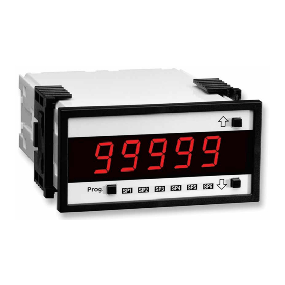
Tiger 320 Series PMCs
5 Digit 0.56" LEDs
in a 1/8 DIN Case
Ethernet, or direct meter-to-meter communications.
0~4 to 20mA or 0 to 10V for retransmission, 4-20mA loops
to drive valve actuators, remote controllers & displays, multi-
loop feedback and PID output. Scalable from 1 count to
full scale.
selectable functions, including latching, deviation, hysteresis,
register resetting, tracking and dual PID. Plus 7 programma-
ble timer modes on all 6 setpoints.
or from any digital input.
relays, logic outputs or open collector outputs. 6 inputs & 16
outputs of opto-isolated I/O can be connected to an external
DIN Rail terminal block module.
time stamp).
TIGER FAMILY: More than 120 different Plug-in
Index . . . . . . . . . . . . . . . . . . . . . . . . . 42-43
Case Dimensions . . . . . . . . . . . . . . . . . . 44
Page 1
Advertisement
Table of Contents

Related Manuals for Texmate DI-50T


Summarization of Contents
General Features
Tiger 320 Operating System
Describes the Tiger 320 OS and its PC-based Configuration Utility Program.
Macro Program Development
Highlights the T Version's support for custom macro programs via the Tiger 320 Macro Development System.
LED Display Specifications
Details the red/green/superbright red 7-segment, 0.56" LEDs with alphanumeric text support.
Modular Construction
Explains the modular design with over 120 interchangeable input signal conditioners and I/O modules.
Input and Processing Capabilities
Covers up to 4 input channels with cross-channel math and sensor excitation voltage outputs.
Calibration and Control Features
Details on-demand tare, calibration, compensation, and autozero maintenance for weighing.
Filtering and Signal Conditioning
Describes programmable input averaging and smart digital filtering for signal response.
Output Options
Covers serial outputs (RS-232, RS-485, Modbus, Ethernet) and analog outputs.
Setpoint and Timer Functions
Details 6 programmable setpoints with 8 functions and 7 programmable timer modes.
Input Module Compatibility
States that over 120 Plug-in I-Series Input Signal Conditioners are approved for the Tiger Family.
Specifications
Display Specifications
Details 7-segment LEDs, range (-19999 to 99999), update rate, and dimming.
Operating System (Tiger 320)
Provides details on the 32-bit processor, flash memory, RAM, EEPROM, and internal bus.
Development System for Custom Macros
Describes the Macro Development System for creating custom software for OEM applications.
Installed Application Software Features
Lists features like Counter Functions, Data Logging, Input Compensation, Math Functions, and Setpoints.
Specifications Continued
Inputs
Details input availability, accuracy, A/D converters, and temperature coefficient.
Outputs
Describes optional carrier boards, analog outputs, and available I/O modules.
Power Supplies and Environmental
Covers power supply options, operating/storage temperatures, and humidity.
Mechanical and Approvals
Details case dimensions, material, weight, and certifications (CE, UL).
Block Diagram of Software and Hardware Structure
Front Panel Button Functions
Explains the function of PROGRAM, F1, F2, F3 buttons and their relation to macro processing.
Register Map Overview
Details the register ranges used for FLASH, serial communication, data logging, and macros.
Core Processing Blocks
Illustrates blocks for Display Drive, Serial Communication, Data Logging, Setpoints, and I/O.
Signal Processing Functions
Shows blocks for Result Processing, Digital Processing, Linearizing, and Totalizers.
Module Interfaces
Diagrams for Smart Modules, Multi-Input Modules, and Single Input Modules.
Controls and Indicators
Front Panel Controls
Describes the PROGRAM, UP, and DOWN buttons and their functions.
Annunciator LEDs
Explains the function of the 6 red LEDs for setpoint indication and alarm status.
Seven Segment LED Displays
Details the 5-digit LED display used for readings and programming codes.
Display Text Editing
Covers editing display text using 7-segment alphanumeric characters via PC connection.
Controls and Indicators Continued
Program Lockout Switch
Explains the switch function to lock programming changes, allowing viewing but not modification.
Setpoint Lockout Switch
Describes the switch to program setpoints and then view them without modification.
Error Message [Err]
Lists common causes for error messages during calibration procedures.
Rear Panel External Switched Inputs
Details functions for LOCK, HOLD, TEST, COMMON, and CAPTURE pins.
Input Pin Functions
Explains the functionality of the LOCK, HOLD, TEST, and CAPTURE pins for remote control.
Front Panel Push Button Configuration and Setup
Programming Conventions
Explains symbols and diagrams used for programming procedures.
Operational Display
Describes the normal operating mode display after power-up.
Button Function Symbols
Defines symbols for PROGRAM, UP, and DOWN buttons used in diagrams.
Front Panel Programming Codes
Main Programming Mode
Accesses all meter functions except setpoints.
Setpoint Programming Mode
Accesses all setpoint and relay functions.
Setpoint Activation Values
Allows adjustment of setpoint activation values.
Setpoint & Relay Control Function Settings
Enables configuration of setpoint control values.
Front Panel Programming Codes Continued
View Modes
Allows viewing of channels, setpoints, peak, and totalizers.
On Demand Modes
Describes activating functions like Tare, Calibration, and Print by pressing the P button.
Initial Setup Procedures
Model and Software Code Version Check
Procedure to check meter model and software version number.
Code Blanking and Macro Check Procedure
Procedure to manage code blanking (tamper-proofing) and macro execution.
Initial Setup Procedures Continued
[bri] - Display Brightness
Configures display brightness level (0-7) and annunciator brightness.
Display Brightness Example Procedure
Step-by-step guide to set the display brightness to 7 (bright).
[CAL] - Calibration Modes for Input and Output
ON DEMAND Functions
Details functions activated on demand via the PROGRAM button.
Calibration Modes
Lists available modes: Manual, Two-point, Thermocouple, RTD, Smart Input, Analog Output.
Calibration Procedures Configuration
Shows configuration for manual, two-point, thermocouple, RTD, and analog output calibration.
[CAL] - Calibration Modes for Input and Output Continued
Related Calibration Functions
Details Serial Communications, Auto Zero Maintenance, Averaging, and Totalizer settings.
Serial Communications Properties
Configures baud rate, parity, time delay, and address settings for serial output.
Set Averaging Samples & Averaging Window
Allows configuring sample count and window size for input signal averaging.
Setup 32-point Linearization Tables
Guides setting up linearization tables for channels 1 to 4.
Scale Analog Output
Procedure for calibrating and scaling the analog output signal.
[CAL] - Calibration Modes for Input and Output Continued
Two-point Calibration
Explains the most common calibration method using low and high input sources.
Two-point Calibration Example Procedure
Step-by-step guide to calibrate channel 1 using the two-point method.
[CAL] - Calibration Modes for Input and Output Continued
Input Signal Filtering and Averaging
Details configuring input signal filtering and averaging parameters.
Input Signal Averaging Example Procedure
Procedure to set averaging rate and window for Channel 1.
[CodE_1] - Display Configuration
CODE 1 – Display Configuration Modes
Explains configuration of display modes, excluding brightness.
Data Source Selection
Configures the data source for primary display and other functions.
Setpoint Annunciators Configuration
Describes how to configure setpoint annunciators to operate.
Update Display at Selected Sample Rate
Allows display update rate to match analog sample rate selected in Code 2.
Manual Loader Mode Configuration
Details configuring the meter to function exclusively as a manual loader.
Display Functions Mode Configuration
Covers configuration of display functions: data source, format, and text.
[CodE_1] - Display Configuration Continued
Display Configuration Digits
Breaks down Code 1 settings into First, Second, and Third Digits for configuration.
Display Format Options
Details options for Last Digit Rounding, Display Units, and Decimal Point Placement.
Select Last Digit Text Character Options
Lists characters available for selection as the last digit text.
[CodE_1] - Display Configuration Continued
Configure Data Source Procedure
Step-by-step guide to select the data source for the third digit display.
Select Data Source Options
Lists available data sources like Primary Display, Peak/Valley, and Analog Output.
[CodE_1] - Display Configuration Continued
Configure Display Format Mode Procedure
Procedure to configure display format for rounding, units, and decimal point placement.
Display Format Mode Options
Details Last Digit Rounding, Display Units (including clock modes), and Decimal Point Placement.
[CodE_1] - Display Configuration Continued
Configure Last Digit Text Character Procedure
Procedure to select the last digit text character for Channel 1 (e.g., 'C' for °C).
[CodE_1] - Display Configuration Continued
Configure Setpoint Annunciators Procedure
Procedure to set annunciators to activate when setpoints are OFF.
Configure Update at Sample Rate Procedure
Procedure to update display at the sample rate selected in Code 2.
[CodE_2] - Channel 1 Measurement Task & Sampling Rate
ANALOG SAMPLE RATE Options
Lists available analog sample rates and output rates for Channel 1.
CODE 2 Options Breakdown
Details First Digit (Sample Rate), Second Digit (Measurement Task), and Third Digit options.
Measurement Task Options
Covers Voltage, Current, TC, RTD, Frequency, Period, Counter, and Smart Input Module tasks.
Frequency Range and Period Measurement Options
Specifies ranges for frequency measurement and options for period measurement.
Counter/Timer/Clock and Smart Input Module Options
Details options for counter, timer, clock, and smart input module configurations.
[CodE_3] - Channel 1 Post Processing & Serial Mode Functions
CH1 Post Processing Options
Lists post-processing functions for Channel 1: direct display, square root, inverse, linearization.
CODE 3 Options Breakdown
Details First Digit (Post Processing), Second Digit (Linearization), and Third Digit (Serial Mode).
Serial Mode Options
Covers ASCII, Modbus, Master, Print, Ethernet, and DeviceNet serial modes.
Print Mode
Describes data logging and printing directly to serial printer or PC.
[CodE_4] - Channel 2 Measurement Task & Sampling Rate
Measurement Task Options
Covers Voltage/Current, TC, RTD, Digital Input tasks for Channel 2.
CODE 4 Options Breakdown
Details First Digit (Measurement Task), Second Digit (Linearization), and Third Digit (Linearization).
FOR VOLTAGE & CURRENT Options
Lists options for Channel 2: Direct, Square Root, Inverse, Output Registers.
Digital Input Options
Details frequency, period, counter, and prescaler settings for digital inputs.
[CodE_5] - Channel 3 Functions
CH3 Post Processing Options
Lists post-processing functions for Channel 3: direct display, square root, inverse, linearization.
CODE 5 Options Breakdown
Details First Digit (Post Processing), Second Digit (Measurement Task), and Third Digit (various options).
Measurement Task Options
Covers No Function, Voltage/Current, TC, RTD, Real Time Clock & Timer, Smart Input Module.
[CodE_6] - Channel 4 Functions
CH4 Post Processing Options
Lists post-processing functions for Channel 4: direct display, square root, inverse, linearization.
CODE 6 Options Breakdown
Details First Digit (Post Processing), Second Digit (Measurement Task), and Third Digit (various options).
Measurement Task Options
Covers No Function, Voltage/Current, TC, RTD, Real Time Clock & Timer, Smart Input Module.
[CodE_7] - Result Processing
Result Processing Digits
Explains how First, Second, and Third digits control math functions between channels.
CODE 7 Options Breakdown
Details First Digit (Result Processing), Second Digit (Linearization), and Third Digit (Math Functions).
Math Functions for Result
Lists math functions like addition, subtraction, ratio, and multiplication for results.
[CodE_8] - Data Logging & Print Mode
Data Log Buffer Types
Describes buffer types: No Logging, Cyclic Buffer, Linear FIFO Buffer, and Reset Buffer.
Data Logging & Print Mode Options
Details Date & Time Stamp options and Log/Print Trigger options.
[CodE_9] - Functions for Digital Input Pins
Display Test Pin Functions
Explains functions of the Display Test pin: test only or reset counters/totals.
Hold Pin Functions
Describes Hold Pin functions: display hold, reset registers, unlatch setpoints.
Lock Pin Functions
Details Lock Pin functions: key lock, reset channels, reset tare, unlatch setpoints.
Setpoint Programming Mode
Setpoint Activation Values Mode
Allows setting individual setpoint activation values within the meter's span range.
Setpoint & Relay Control Settings Mode
Provides access to configure relay energize, activation source, and delay/reset functions.
Relay Output Modules
Details available relay output module options (SSRs, electromechanical, opto-isolated).
Setpoint Programming Mode Continued
Relay Energize Functions
Configures relays to energize above or below the setpoint value.
Setpoint Activation Source
Allows setpoints to activate from input channels, registers, or digital inputs.
Setpoint Latching
Enables programming setpoints in relay latching modes.
PID Control Settings
Details the PID control function for stable control in process applications.
Timer Modes
Provides seven resident timer modes for setpoint relay operation.
Hysteresis or Deviation
Allows programming hysteresis or deviation for setpoint relay energization.
Setpoint Programming Mode Continued
Deviation (Passband) Function
Describes the deviation band around setpoint for relay energization.
Pulse OFF Mode (Programmable OFF-time)
Configures single actuation with programmable off time and delay-on-break.
Relay Time Control Modes
Explains Normal Mode, Pulsed ON/OFF Modes, and 1-Shot modes for relay timers.
Level 1 - Setpoint & Relay Basic Mode
Basic mode for relay energize, activation source, and latching functions.
Level 2 - Setpoint & Relay Intermediate Mode
Intermediate mode adding Hysteresis, Deviation, PID, and Timer functions.
Level 3 - Setpoint & Relay Advanced Mode
Advanced mode incorporating reset and trigger functions for complex operations.
Setpoint Programming Mode Continued
Level 1 - Basic Mode Programming Procedures
Step-by-step guide for programming setpoint 1 (SP1) functions.
Setpoint Programming Mode Continued
Setpoint & Relay Control Settings Diagram
Diagram showing 1st, 2nd, and 3rd digit control settings for setpoints and relays.
Set Up Hysteresis, Deviation & PID Mode Settings
Guides setting hysteresis, deviation, PID parameters, and advanced functions.
Setpoint Span and Bandwidth Settings
Covers setting the span, proportional band, integral, and derivative values.
Setpoint Programming Mode Continued
Set Up Timer Delay Settings
Details configuration for various timer delay modes (Normal, 1-Shot, Pulse, Repeat).
Set Up Register Reset and Setpoint Trigger Functions
Guides setting up register reset destinations, print/log triggers, and reset constants.
Registers Selectable by Front Panel Programming
40 Manually Selectable Registers
Lists 40 registers selectable for display, setpoint, totalizer, and analog output functions.
Resetting and Incrementing Using Setpoints
Explains how setpoints can be used to reset or increment registers for counting.
Functional Diagram
Input Signal Conditioning Module Socket
Diagram showing the connection socket for input signal conditioning modules.
Processor, Carrier, and Relay Boards
Layout of main internal boards: Processor, Carrier, and Relay Modules.
Output Modules and Serial/Analog Connections
Shows connections for Serial Output, Analog Output, and Relay/Logic I/O modules.
Rear Panel Pinout Diagram
Diagram detailing rear panel connections for inputs, outputs, and function pins.
Function Pins Description
Explains the function of pins like PROGRAM LOCK, HOLD, TEST, CAPTURE, and COMMON.
Carrier Board Output Pins
Analog and Serial Output Pinouts
Details pins for Analog Outputs (16, 17, 18) and Serial Outputs (19-24).
Relay Module Pinout Diagrams
Shows pin assignments for SSR, 4A Form A, 5A Form A, and 9/10A Form C relay modules.
Open Collector / TTL / 5VDC Output Module
Details pinout for the 5VDC output module with 50 mA capability.
Relay and Logic I/O Module Pinouts
Shows pinouts for Opto Isolated I/O modules and their breakout box.
Component Layout and External Devices
Modular Construction Overview
Explains the meter's modular design for automation and process control applications.
Base Meter Components
Illustrates the 320 Series Base Meter with Power Supply, Processor, and Display.
Input Signal Conditioning Modules
Describes the selection of over 120 single, dual, triple, or quad input signal types.
Carrier Board Options
Details Standard Serial Output and Optional Ethernet Carrier Boards.
Output Module Types
Lists Relay Modules (Electromechanical, Solid State) and I/O Modules.
Pin Assignments for Outputs
Shows pin assignments for Relay Output Pins, NPN Open Collector Outputs, and Serial/Analog Pins.
Component Layout and External Devices Continued
Main PCB and Module Connections
Diagrams the Main PCB, Processor Board, Display Board, and module connections.
Analog Output Module PCB
Details the PCB for Analog Output Modules, including Current/Voltage selection.
Serial Output Module PCBs
Shows PCBs for Standard Serial Output Modules (RS-232/RS-485).
Opto Isolated I/O Modules Connection
Illustrates connecting Opto Isolated I/O Modules to a DIN Rail Breakout Box.
Installation Guidelines
Installation Procedures
Provides guidelines for meter installation, wiring, and environmental considerations.
Index Entries
Macros and Manual Loader
Index entries for Macro Check and Manual Loader functions.
Math Functions and Serial Communication
Index entries for Maths Functions, Modbus, and Serial Communication configuration.
Setpoint Programming Mode Overview
Index entries covering Setpoint Mode, Data Logging, Hysteresis, PID, and Timer functions.
Input Signal and Module Configuration
Index entries for Input Signal Sample Rate, Smart Input Modules, and I/O Modules.
Index Entries Continued
Programming Codes and Registers
Index entries for Programming Codes, Registers, and Setpoint Programming Mode.
Serial Communication and Setpoint Functions
Index entries for Serial Communication, Setpoint Modes, and Timer Modes.
Case Dimensions
Panel Cutout and Fitting Dimensions
Details panel cutout sizes and fitting dimensions for 1/8 DIN cases.
Case Views and Component Details
Illustrates Top, Side, and Front views, including key-lock socket and safety catch.
Warranty and User Responsibility
Provides warranty information and outlines user responsibilities.
Need help?
Do you have a question about the DI-50T and is the answer not in the manual?
Questions and answers