Table of Contents
Advertisement
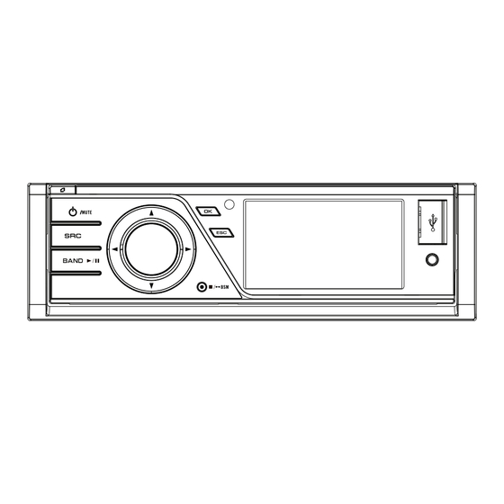
DVD AV RECEIVER
DVH-730AV
DVH-735AV
DVH-735AV
DVH-7380AV
For details, refer to "Important Check Points for Good Servicing".
PIONEER CORPORATION
PIONEER ELECTRONICS (USA) INC. P.O. Box 1760, Long Beach, CA 90801-1760, U.S.A.
PIONEER EUROPE NV Haven 1087, Keetberglaan 1, 9120 Melsele, Belgium
PIONEER ELECTRONICS ASIACENTRE PTE. LTD. 253 Alexandra Road, #04-01, Singapore 159936
PIONEER CORPORATION 2011
1-1, Shin-ogura, Saiwai-ku, Kawasaki-shi, Kanagawa 212-0031, Japan
DVH-730AV/XZUW5
/XZRD
/XZRI
/XFBR
PROVISIONAL
CRT4714P
/XZUW5
K-ZZZ JULY 2011 Printed in Japan
Advertisement
Table of Contents

Related Manuals for Pioneer DVH-7380AV


Summarization of Contents
Pioneer Service Manual
Safety Information
Crucial safety instructions for technicians and product operation, covering laser and battery handling.
Service Precautions
General Service Precautions
Guidelines on regulations, sharp edges, IC handling, and metal parts.
Soldering Notes
Recommendations for lead-free solder use and soldering iron temperature settings.
Product Specifications
General and Display Specifications
Details on power source, dimensions, weight, screen size, and display methods.
Disc and Content Formats
Logos and list of supported media formats like DVD, CD, WMA, MP3, DivX.
Service Operations
Post-Servicing Checks
Essential checks to confirm solved complaints, normal operations, and product appearance.
PCB Locations
Diagrams showing PCB positions and a list of required jigs for servicing.
Jigs List
List of specific jigs required for servicing procedures.
Cleaning Procedures
Instructions for cleaning specific parts like DVD pickup lenses using prescribed tools.
System Diagrams
Overall Block Diagram
Visual representation of the unit's main functional blocks and their interconnections.
Power Block Diagram
Detailed illustration of the power supply paths and current consumption for each section.
Diagnosis and Troubleshooting
Operational Flowchart
Step-by-step logic for power-on operation sequence and initial checks.
Error Code List
Comprehensive list of error messages, their causes, and recommended corrective actions.
Connector Function Description
Description of external connector pinouts and their designated functions.
Service Mode and Disassembly
Software Version Information Display
Procedure to access and display the unit's software and firmware versions.
Component Disassembly Guide
Step-by-step instructions for removing the case, mechanism, panel, and mother unit.
Stuck Disc Ejection Procedures
Manual procedures to safely remove a disc that is stuck in the player mechanism.
Parts and Schematics
Exploded Views and Packing Parts
Visual breakdown of assemblies with lists of part numbers for packing.
Exterior Parts Lists
Detailed parts lists and contrast tables for exterior components.
Mechanism Parts List
Lists parts and contrast table for the DVD mechanism assembly.
Mother Unit Schematics
Detailed electrical schematics for the Mother Unit (1/2) and (2/2).
DVD Decode Unit Schematics
Detailed schematics for the DVD Decode Unit, covering power and main parts.
DVD Decode Unit Power Schematics
Detailed schematics for the DVD Decode Unit's power supply section.
DVD Decode Unit Main Schematics
Detailed schematics for the main board of the DVD Decode Unit.
Keyboard and AUX PCB Schematics
Detailed schematics for the Keyboard PCB and AUX PCB.
LB PCB and CB PCB Schematics
Schematics and connection diagrams for the LB PCB and CB PCB.
KB-SB PCB Diagram
Connection diagram for the KB-SB PCB, showing connectors and pin assignments.
PCB Connection Diagrams
Mother Unit Connections
Diagrams illustrating PCB component layouts and connector interconnections for the Mother Unit.
DVD Decode Unit Connections
PCB layout and component placement for the DVD Decode Unit (Side A and Side B).
Keyboard PCB Connections
PCB layout and component placement for the Keyboard PCB (Side A and Side B).
AUX PCB Connections
PCB layout showing signal routing and connector for the AUX PCB (Side A and Side B).
LB PCB Layout
Diagram showing component placement and switch/LED locations on the LB PCB.
KB-SB PCB Layout
PCB layout diagrams for the KB-SB PCB, showing connectors and component placement.
Electrical Parts List
Component Part Numbers
Comprehensive list of all electrical components, including resistors, capacitors, ICs, and diodes, with their part numbers.
Need help?
Do you have a question about the DVH-7380AV and is the answer not in the manual?
Questions and answers