
Related Manuals for Knikmops KM 130


Summary of Contents for Knikmops KM 130
- Page 1 User instructions Knikmops wheel loader KM 80, KM 85, KM 90, KM 100, KM 120, KM 125, KM 130 and KM 170...
- Page 2 Contact details Gebroeders Geens N.V. Hinnenboomstraat 5 2320 Hoogstraten (Belgium) Tel. +32 (0)3-314 79 30 Fax +32 (0)3-314 84 56 E-mail: info@knikmops.be...
-
Page 3: Table Of Contents
Table of Contents Table of Contents 1. Introduction_______________________________________________________________________________ 1 About these instructions_______________________________________________________________ 1 Version history_________________________________________________________________________1 Target group___________________________________________________________________________ 1 Symbols used__________________________________________________________________________ 2 2. Machine numbers_________________________________________________________________________ 3 Machine identification_________________________________________________________________ 3 Type plate______________________________________________________________________________3 3. Intended use______________________________________________________________________________ 4 4. Safety______________________________________________________________________________________5 Safety instructions_____________________________________________________________________ 5 4.1.1 Instructions before use of the machine and attachments____________________ 5 4.1.2 Instructions for the user______________________________________________________7... - Page 4 Table of Contents Operator's seat_______________________________________________________________________ 22 Starting_______________________________________________________________________________ 22 6.2.1 Preparatory work___________________________________________________________ 22 6.2.2 Starting a machine with a Kubota engine___________________________________ 23 6.2.3 Starting a machine with a Yanmar engine___________________________________ 24 Stopping______________________________________________________________________________ 24 6.3.1 Stopping a machine with a Kubota engine__________________________________ 24 6.3.2 Stopping a machine with a Yanmar engine__________________________________ 25 Driving________________________________________________________________________________26...
- Page 5 Table of Contents 6.11.2 Removing the articulation lock______________________________________________ 48 6.12 Preheating____________________________________________________________________________ 49 7. Attachment – bucket_____________________________________________________________________ 50 Overview_____________________________________________________________________________ 50 Commissioning_______________________________________________________________________ 50 Coupling______________________________________________________________________________ 50 Using_________________________________________________________________________________ 51 Driving________________________________________________________________________________51 Uncoupling___________________________________________________________________________ 51 8. Attachment – pallet fork__________________________________________________________________ 52 Overview_____________________________________________________________________________ 52 Commissioning_______________________________________________________________________ 52 Coupling______________________________________________________________________________ 52 Using_________________________________________________________________________________ 53 Driving________________________________________________________________________________53 Uncoupling___________________________________________________________________________ 54...
- Page 6 Table of Contents 10.8 Checking the parking brake___________________________________________________________67 10.9 Lubricating the hinge points__________________________________________________________ 68 10.9.1 Location of the lubrication nipples – standard version______________________ 68 10.9.2 Location of the lubrication nipples – TE version_____________________________ 69 10.9.3 Location of other lubrication points_________________________________________ 70 10.9.4 Lubricating via the lubrication nipples______________________________________ 70 10.10 Checking/topping up the engine oil___________________________________________________71...
- Page 7 Table of Contents 14.1 Consumables_________________________________________________________________________ 88 14.2 Machine dimensions_________________________________________________________________ 89 14.3 Maximum machine load______________________________________________________________ 92 14.4 Other technical machine data________________________________________________________ 94 14.5 Sound level___________________________________________________________________________ 97 14.6 Bucket dimensions___________________________________________________________________ 97 14.7 Pallet fork dimensions________________________________________________________________ 99 15. Options and attachments_______________________________________________________________ 100 15.1 Options______________________________________________________________________________100 15.2 Attachments_________________________________________________________________________102...
-
Page 9: Introduction
– pallet fork, volume buckets, shovel buckets, and rubble buckets. The Knikmops wheel loader is referred to as the "machine" in these instructions. The volume buckets, shovel buckets, and rubble buckets are referred to as the "buckets"... -
Page 10: Symbols Used
Introduction Symbols used The following symbols are used in this document: Symbol Function Description "Warning" means that there is a risk of physical injury or death Warning! if the instructions are not followed. "Caution" means that there is a risk of damage to the Caution equipment if the instructions are not followed. -
Page 11: Machine Numbers
Engine number: Color: Delivery date: Stamp of accredited Knikmops distributor: Type plate The figure below shows an example type plate on the machine or the attachment. The actual type plate shows the correct data according to the type of machine or... -
Page 12: Intended Use
Intended use 3. Intended use The machine has been designed for work and transportation activities in road construction, garden landscaping, and related industries. Attachments can be coupled to and uncoupled from the machine for use in different applications. Only use attachments that are intended for your machine and that have been approved by the manufacturer. -
Page 13: Safety
Safety 4. Safety Safety instructions 4.1.1 Instructions before use of the machine and attachments • Read the instructions carefully before using the machine. • Ensure that no one is at risk. • Carry out the procedures fully and in the specified order. •... - Page 14 Safety • Stow materials and tools when not in use. • Avoid prolonged overloading of the hydraulic systems. Failure to do so will cause the machine to overheat. Always move the hydraulic control of the machine to the neutral position when starting up. •...
-
Page 15: Instructions For The User
Safety 4.1.2 Instructions for the user • Only personnel who have been trained by the manufacturer or importer are permitted to use, maintain, and repair the attachments. • Personnel must: - be eighteen years of age or older. - be physically and mentally healthy. - have the requisite knowledge and skills. - Page 16 Safety • Avoid turning the steering wheel when the machine is stationary. • Never transport people with the machine or attachments. • Do not make sharp turns at high speed. • Keep the safety belt on at all times. • If you notice that the machine is becoming unstable or skidding, stop the machine as promptly as possible with the attachment on the ground.
-
Page 17: General Safety Instructions
Safety • Lifting and hoisting equipment must not be used if it has not been inspected or not inspected promptly. • When the machine is stationary, operations under the attachment, whether the attachment is laden or unladen, are not permitted. 4.1.4 General safety instructions •... -
Page 18: Safety Symbols On The Machine
Safety Safety symbols on the machine The safety symbols on the machine and the attachments must always be legible and be replaced if damaged. 4.2.1 General safety symbols Symbol Description Personnel not operating the machine must stay out of its vicinity. Safety instructions that you must read before starting the machine. - Page 19 Safety Symbol Description Install the FOPS if there is a risk of falling objects. Safety instructions on what to do when the machine tips over. Use hydraulic fluid only. Safety instructions that you have to read carefully to avoid injury or death. Never remove the ROPS.
- Page 20 Safety Symbol Description Always read the operator manual and safety instructions. Maintain 3-point contact during entry and exit if your are the operator and keep a safe distance from the machine during entry and exit if you are not the operator. Risk of burns: beware of hot machine parts.
-
Page 21: Description Of Components
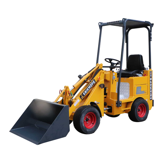
Description of components 5. Description of components Overview Figure 1: Overview of the machine Safety cab (compulsory when working on Accelerator pedal slopes or where there is a risk of falling materials) Lifting eyelets for hoisting the machine Operator's seat with a safety cab Parking brake Counterweights (optional) Steering wheel... -
Page 22: Dashboard
Description of components Dashboard Different dashboard types are available according to the machine. 5.2.1 Dashboard type 1 – standard version Figure 2: Overview of dashboard type 1 – standard version Ignition key Glow plug lamp for the diesel engine Shurlock button (only for the Engine temperature lamp "hydraulically operated locking pin on the connector plate"... -
Page 23: Dashboard Type 2
Description of components 5.2.2 Dashboard type 2 Figure 3: Overview of dashboard type 2 Ignition key Neutral position indicator Fuse box Glow plug lamp for the diesel engine Shurlock button (only for the Direction indicator "hydraulically operated locking pin on the connector plate"... -
Page 24: Hydraulic Operation
Description of components Hydraulic operation 5.3.1 Hydraulic operation – standard version Figure 4: Hydraulic operation – standard version Cross lever Lever for hydraulic assistance function, right Lever for hydraulic assistance function, left If the machine is equipped with a hydraulically operated locking pin, the "lever for hydraulic assistance function, left"... -
Page 25: Hydraulic Operation - Ehc Version
Description of components Figure 5: Hydraulic operation – TE version Horn High/low adjustment button (only on types KM 125 and KM 250) Travel direction button Lever for hydraulic assistance function, left Telescope button Lever for hydraulic assistance function, right Spare button (optional: horn) 5.3.3 Hydraulic operation –... - Page 26 Description of components Figure 6: Hydraulic operation – eHC version Button for hydraulic function, A direction Flow control Travel direction button Switch for locking the right-hand function Spare button (optional: horn) Switch for selecting fixed stop or double action Button for hydraulic function, B direction High/low transmission button (types KM125 and KM250 only) or laser function on/off switch...
-
Page 27: Sticker For Hydraulic Operation
Description of components 5.3.4 Sticker for hydraulic operation Figure 7: Sticker for hydraulic operation Lower arm Hydraulic assistance function, right Raise arm Hydraulic assistance function, left Connector plate, front Hydraulic pressure on hydraulic connection side with red dust cap Connector plate, rear Hydraulic pressure on hydraulic connection side with green dust cap... -
Page 28: Connector Plate
Description of components Connector plate 5.4.1 Connector plate with manually operated locking pin Figure 8: Connector plate with manually operated locking pin Connection for hydraulic assistance Locking pin function, right Connection for hydraulic assistance Locking lever function, left Plate of connector plate... -
Page 29: Connector Plate With Hydraulically Operated Locking Pin
Description of components 5.4.2 Connector plate with hydraulically operated locking pin Figure 9: Connector plate with hydraulically operated locking pin Connection for hydraulic assistance Plate of connector plate function, left Connection for hydraulic assistance Locking pins function, right... -
Page 30: Operating The Machine
Operating the machine 6. Operating the machine Operator's seat The illustration below is a standard depiction of the operator's seat. A different operator's seat may be optionally requested. Please contact your distributor for more information. If you opt to use a different operator's seat, follow the instructions supplied with that seat. -
Page 31: Starting A Machine With A Kubota Engine
Operating the machine For more information on how to check the fuel tank, see Checking the fuel tank on page For more information on how to top up the hydraulic fluid, see Checking/ topping up the hydraulic fluid on page If you are working in a dusty environment, ensure that the cyclone filter is still usable. -
Page 32: Starting A Machine With A Yanmar Engine
Operating the machine Turn the key to the GL position. Wait until the glow plug lamp goes out. Turn the key to the ST position. The key returns to the ON position 6.2.3 Starting a machine with a Yanmar engine Once you have completed all preparatory work, you can start the machine. -
Page 33: Stopping A Machine With A Yanmar Engine
Operating the machine Figure 13: Kubota engine ignition Bring the machine to a halt on a level surface, if possible. Do one of the following: - Lower the arm to the ground if no load is present. - Place the load against the ground. Pull the parking brake upward as far as it will go. -
Page 34: Driving
That way, the engine speed of the Knikmops is separate from the actual travel speed. This means you can adjust the speed of a specific attachment without changing the speed of the... -
Page 35: Locking Differential
Operating the machine You can use the inching pedal at the same time as the accelerator pedal or clutch pedal in order to drive slowly over uneven ground, for example, or to drive slowly to lift heavy loads. The inching pedal itself has no effect on the speed of the engine. - Page 36 Operating the machine If your machine is equipped with an electronic locking differential control, press the button on the dashboard to switch the locking differential off and Figure 16: Locking differential Turn the locking differential adjustment button (A) clockwise as far as it will go to switch the differential on.
-
Page 37: Driving: Standard Version
Operating the machine 6.4.3 Driving: standard version Figure 17: Driving: standard version Warning! If you notice that the machine is becoming unstable or skidding, stop the machine as quickly as possible with the attachment on the ground. Press the button on the parking brake and push the parking brake down as far as it will go. -
Page 38: Driving - Te Version
Operating the machine 6.4.4 Driving - TE version Figure 18: Driving - TE version Warning! If you notice that the machine is becoming unstable or skidding, stop the machine as quickly as possible with the attachment on the ground. This version is also available as an option for other types. In that case, the standard VNA switch is omitted. - Page 39 Operating the machine Release the accelerator pedal again and depress the inching pedal to brake.
-
Page 40: Driving: Ehc Version
Operating the machine 6.4.5 Driving: eHC version Figure 19: Driving: eHC version Warning! If you notice that the machine is becoming unstable or skidding, stop the machine as quickly as possible with the attachment on the ground. This version is also available as an option for other types. In that case, the standard VNA switch is omitted. -
Page 41: Operating The Arm
Operating the machine Use the driving direction button to change machine's gear. This function is standard on types KM125 and KM250 and optional on other types. Release the accelerator pedal again and depress the inching pedal to brake. Operating the arm An arm is the lifting section of the machine. -
Page 42: Operating The Arm - Standard Version
Operating the machine 6.5.1 Operating the arm – standard version Figure 20: Operating the arm – standard version Push the arm lever (A) forward (1) to lower the arm. Pull the arm lever (A) backward (2) to raise the arm. Pull the arm lever (A) to the left (3) to tilt the connector plate backward. Push the arm lever (A) to the right (4) to tilt the connector plate forward. -
Page 43: Operating The Arm - Te Version
Operating the machine 6.5.2 Operating the arm – TE version Figure 21: Operating the arm – TE version This version is also available as an option for other types. In that case, the telescope button will be non-functional. Push the arm lever (A) forward (1) to lower the arm. Pull the arm lever (A) backward (2) to raise the arm. -
Page 44: Coupling An Attachment
Operating the machine Figure 22: Operating the arm – eHC version Push the arm lever (A) forward (1) to lower the arm. Pull the arm lever (A) backward (2) to raise the arm. Pull the arm lever (A) to the left (3) to tilt the connector plate backward. Push the arm lever (A) to the right (4) to tilt the connector plate forward. - Page 45 Operating the machine Figure 23: Coupling with a manually operated locking pin Drive the machine up to the attachment that you wish to couple. Lower the arm as low to the ground as possible. Tilt the connector plate (C) forward. Drive the machine forward until the connector plate makes contact with the attachment.
-
Page 46: Coupling With A Hydraulically Operated Locking Pin
Operating the machine A hydraulically operated locking pin may also be installed on a connector plate with manually operated locking pin. 6.6.3 Coupling with a hydraulically operated locking pin Start by releasing the hydraulic pressure. For more information, see Releasing the hydraulic pressure on page 36. -
Page 47: Uncoupling An Attachment
Operating the machine Choose one of the following options based on your dashboard type: - Press and hold the corresponding button on dashboard type 1 so that the locking pins temporarily retract. For more information, see button B in Dashboard type 1 – standard version on page - Press and hold the corresponding button on dashboard type 2 so that the locking pins temporarily retract. -
Page 48: Uncoupling With A Hydraulically Operated Locking Pin
Operating the machine Figure 25: Uncoupling with a manually operated locking pin Place the attachment on the ground. If hydraulic assistance functions are connected, proceed as follows: - Switch the machine off completely. - Move the lever to operate the hydraulic assistance function that you wish to release back and forth to allow the pressure to escape from the hydraulic assistance functions. - Page 49 Operating the machine Figure 26: Uncoupling with a hydraulically operated locking pin Place the attachment on the ground. If hydraulic assistance functions are connected, proceed as follows: - Switch the machine off completely. - Move the lever to operate the hydraulic assistance function (C) that you wish to release back and forth to allow the pressure to escape from the hydraulic assistance functions.
-
Page 50: Checking The Fuel Tank
Operating the machine Checking the fuel tank If you want to know how much fuel remains in the tank, there are two options. 6.8.1 Checking the fuel tank with dashboard type 1 For more information on the dashboard type that you have, see Dashboard on page Turn the ignition key to the OFF position to switch the engine off. -
Page 51: Filling The Fuel Tank
Operating the machine Filling the fuel tank Warning! The fuel is flammable and may be hazardous. Exercise caution when handling fuel and fill in a well-ventilated area away from naked flames and sparks. Warning! Do not smoke while filling. Caution! The fuel tank must never be allowed to run dry. - Page 52 Operating the machine Remove the tank cap (A). Fill the fuel tank and refit the tank cap. Caution! Do not allow fuel to drip onto the machine. In the event of a spillage, clean it immediately.
-
Page 53: Fitting Counterweights
A minimum of two people are required to lift the counterweights. Each counterweight has a weight of more than 30 kg. Fit only genuine parts developed for Knikmops to the rear of the machine. Warning! People are not allowed to stand at the rear of the machine to act as counterweights. -
Page 54: Installing The Second And Third Weight
Operating the machine 6.10.2 Installing the second and third weight Figure 29: Installing the second and third weight Suspend the counterweight (A) from the first counterweight using the hook (B). Fit the counterweight with the locking bolts (C). -
Page 55: Installing And Removing The Articulation Lock
Operating the machine 6.11 Installing and removing the articulation lock The articulation lock prevents the machine from articulating in the event of a problem with the steering system. 6.11.1 Fitting the articulation lock Figure 30: Fitting the articulation lock Turn the ignition key to the OFF position to switch the engine off. Remove the bolt (A). -
Page 56: Removing The Articulation Lock
Operating the machine 6.11.2 Removing the articulation lock Figure 31: Removing the articulation lock Remove the bolt (A). Turn the articulation lock (B) toward the front of the machine. Use the bolt (A) to refit the articulation lock to the machine. -
Page 57: Preheating
Operating the machine 6.12 Preheating The machine may be fitted with an optional preheating element. The figure in this section shows the cable connection for the KM 100. Figure 32: Connecting the cable to allow the machine to be preheated Take the supplied cable (A) and connect the machine to the socket and the connection point (B) on the machine. -
Page 58: Attachment - Bucket
Attachment – bucket 7. Attachment – bucket Overview Figure 33: Example bucket Commissioning Before coupling the attachment to the machine, a number of items must be checked: • The machine has sufficient capacity to be equipped with the attachment in all potential situations, e.g., when pivoting or rotating. -
Page 59: Using
Attachment – bucket Using Pay close attention to the bucket while handling it. A bucket that is hanging too low may permanently damage the ground and the bucket. Driving with the bucket raised high poses a risk of tipping. Caution! You must warn persons nearby that they must stay away from the area of the load. -
Page 60: Attachment - Pallet Fork
Attachment – pallet fork 8. Attachment – pallet fork Overview Figure 34: Example pallet fork Commissioning Before coupling the pallet fork to the machine, a number of items must be checked: • The machine has sufficient capacity to be equipped with the attachment in all potential situations, e.g., when pivoting or rotating. -
Page 61: Using
Attachment – pallet fork Using Please familiarize yourself with the safety instructions before using the attachment. For more information, see Safety instructions on page Driving Set the loading buckets to the correct width for the pallet you wish to transport: Unlock the pallet fork by rotating the latch (see drawing) 90°... -
Page 62: Uncoupling
Ensure that the load is as close to the center of the pallets as possible so that you can raise the load as centrally as possible. This is better for the stability and load on the Knikmops. Warning! Driving with the load raised high poses a risk of tipping. -
Page 63: Transport And Storage
Transport and storage 9. Transport and storage Transportation – safety instructions • Do not tow the machine. • Do not expose the machine to external shocks, vibrations, or impact. • Protect the machine from external influences, such as rain, splashing (salt) water, dirt, and dust. -
Page 64: Storage
Transport and storage Always fit the articulation lock if there is a problem with the steering system. For more information, see Fitting the articulation lock on page Attach the lifting equipment to the lifting eyelets. Caution! The lifting equipment must not make contact with the hydraulic control. Caution! The lifting chains or straps must all be of the same length so that the machine remains horizontal during lifting. -
Page 65: Maintaining The Machine
Maintaining the machine 10. Maintaining the machine 10.1 Daily maintenance The operator of the machine or someone with an equivalent level of training may carry out daily maintenance. Warning! Do not touch hot parts of the machine, such as the engine, exhaust, and hydraulic system. -
Page 66: Maintenance Table - Maintenance Of Machine When Switched Off
Maintaining the machine 10.2 Maintenance table – maintenance of machine when switched off Machine part Procedure Rejection criterion Action on rejection Visually inspect for Damage or sharp Contact an accredited damage or sharp objects on in the tires. maintenance engineer. objects on in the tires. -
Page 67: Maintenance Table - Maintenance Of Machine When Switched On
Maintaining the machine Machine part Procedure Rejection criterion Action on rejection Check the tension. The belt moves more For more information, Contact an accredited Fan belt than 9 mm or less than see Checking the maintenance engineer. 7 mm. fan belt tension on page Safety stickers Check legibility. - Page 68 Maintaining the machine Frequency Activity Procedure See the operating instructions Replace the engine oil. for the diesel engine. See the operating instructions Replace the engine oil filter. for the diesel engine. See the operating instructions First 50 hours Drain the water separator. for the diesel engine.
- Page 69 Maintaining the machine Frequency Activity Procedure For more information, see Replace the hydraulic fluid Replacing hydraulic fluid filters on page For more information, see Every 1,200 hours Replace the fine filter. Replacing the air and fine filter on page For more information, see Replace the return filter.
-
Page 70: Opening The Engine Compartment
Maintaining the machine 10.5 Opening the engine compartment Warning! Do not touch hot engine parts. The engine compartment may only be opened when the engine is stationary. The procedure for opening the engine compartment depends on the type of machine. Check the machine type and select the correct procedure. 10.5.1 Opening the engine compartment –... -
Page 71: Opening The Engine Compartment - Type 2
Maintaining the machine 10.5.2 Opening the engine compartment – type 2 Figure 37: Opening the engine compartment – type 2 TE version Set the lever (A) to the horizontal position. Open the cover (B). Pull the lever (C) and open the cover, including the operator's seat (D). -
Page 72: Opening The Engine Compartment - Type 3
Maintaining the machine 10.5.3 Opening the engine compartment – type 3 Engine compartment type 3 is an obsolete model and is no longer in production. Figure 38: Opening the engine compartment – type 3 eHC version Set the lever (A) to the horizontal position. Open the cover, including the operator's seat (B). - Page 73 Maintaining the machine Figure 39: Cyclone filter Undo the wing nut (A) on the cover. Remove the wing nut, the cover (B), and the filter housing (C) in that order. Clean the filter housing with compressed-air or water. If you clean the filter housing with water, ensure that the filter housing is completely dry after cleaning.
-
Page 74: Checking The Fan Belt Tension
Maintaining the machine 10.7 Checking the fan belt tension Switch the machine off to check the tension of the belt. Allow the machine to cool sufficiently before starting. Figure 40: Kubota fan belt tension... -
Page 75: Checking The Parking Brake
Maintaining the machine Figure 41: Yanmar fan belt tension Open the engine compartment. For more information, see Opening the engine compartment on page Use your thumb to press on the belt (A) at the longest span. There should be between 7 and 9 mm of play. If the belt moves more or less than the permitted play, contact a recognized maintenance engineer. -
Page 76: Lubricating The Hinge Points
Maintaining the machine 10.9 Lubricating the hinge points 10.9.1 Location of the lubrication nipples – standard version Figure 42: Location of the lubrication nipples – standard version Lubrication nipple, center Lubrication nipple, left Lubrication nipple, right... -
Page 77: Location Of The Lubrication Nipples - Te Version
Maintaining the machine 10.9.2 Location of the lubrication nipples – TE version Figure 43: Location of the lubrication nipples – TE and eHC version Lubrication nipple Lubrication nipple for a horizontal, hydraulically operated locking pin. -
Page 78: Location Of Other Lubrication Points
Maintaining the machine 10.9.3 Location of other lubrication points Figure 44: Location of other lubrication points Lubrication nipple 10.9.4 Lubricating via the lubrication nipples Before you begin: Ensure that you have a grease gun to hand. Attach the grease gun to a lubricating nipple. Inject lubricating grease using the grease gun until it begins to emerge from the bearing. -
Page 79: Checking/Topping Up The Engine Oil
Maintaining the machine 10.10 Checking/topping up the engine oil 10.10.1 Checking the engine oil level Warning! The engine must be off while carrying out this procedure. Allow the engine to cool down sufficiently. Figure 45: Checking the engine oil level – Kubota Figure 46: Checking the engine oil level –... -
Page 80: Topping Up The Engine Oil
Maintaining the machine Remove the engine oil dipstick from the holder again. Verify that the engine oil level is between the MIN and MAX markings. If the engine oil level is too low, follow the steps in Topping up the engine oil on page Insert the engine oil dipstick back into the holder. - Page 81 Maintaining the machine Figure 48: Topping up Yanmar engine oil Open the engine compartment. For more information, see Opening the engine compartment on page Remove the engine oil cap (B). Top up the oil tank and wait for five minutes. For the correct type of engine oil, see Consumables on page Remove the engine oil dipstick (A) from the holder.
-
Page 82: Checking/Topping Up The Coolant
Maintaining the machine 10.11 Checking/topping up the coolant 10.11.1 Checking the coolant level Warning! The engine must be off while carrying out this procedure. Allow the engine to cool down sufficiently. Figure 49: Checking the coolant level – Yanmar and Kubota Open the engine compartment. -
Page 83: Checking/Topping Up The Hydraulic Fluid
Maintaining the machine Figure 50: Topping up the coolant Open the engine compartment. For more information, see Opening the engine compartment on page Remove the cap (A) from the radiator. Allow excess pressure to escape before fully removing the cap. Top up the coolant to the FULL mark on the reservoir. For the correct type of coolant, see Consumables on page Screw the cap back onto the radiator. -
Page 84: Checking The Hydraulic Fluid Level
Maintaining the machine Figure 51: Checking/topping up the hydraulic fluid 10.12.1 Checking the hydraulic fluid level Verify that the fluid level in the sight glass (C) is between the MIN and MAX markings. If the fluid level is too low, top up the hydraulic fluid. For more information, see Topping up the hydraulic fluid on page Contact a recognized maintenance engineer if the fluid level is too low. -
Page 85: Replacing The Air Filter
Maintaining the machine 10.13 Replacing the air filter Please contact the manufacturer for the correct replacement parts. Only an accredited maintenance engineer may carry out this procedure. It is recommended that the air filter be replaced whenever maintenance is carried out. 10.13.1 Removing the cover Figure 52: Removing the cover from the air filter... -
Page 86: Replacing The Air And Fine Filter
Maintaining the machine 10.13.2 Replacing the air and fine filter Figure 53: Replacing the air filter Remove the old air filter (B). Remove the old fine filter (C). Fit the new fine filter (C). Fit the new air filter (B). Replace the cover (A) and turn it clockwise until the retaining clip engages. Close and lock the engine compartment. -
Page 87: Replacing The Suction Filter
Maintaining the machine 10.14.1 Replacing the suction filter Figure 54: Replacing the suction filter Remove the side panel (A). Place a contain under the release cap (B). Remove the release cap. Result: hydraulic fluid runs from the release opening. Remove the suction filter (C). Replace the side panel. -
Page 88: Replacing The Return Filter
Maintaining the machine 10.14.2 Replacing the return filter The return filter filters all oil that is returned from the system, shortly before it enters the hydraulic tank again. The return filter is only fitted on certain machine types. The return filter should only be replaced by a recognized maintenance engineer or dealer. -
Page 89: Cleaning The Machine
Maintaining the machine Always use new hydraulic fluid when topping up. 10.15 Cleaning the machine You must clean the machine at regular intervals. That way, you will keep the machine in good condition and make it easier to operate the arm and other controls. - Page 90 Maintaining the machine Problem Cause The cleaning agent has had a corrosive effect on The machine has a mat appearance after drying. the paint. This is usually due to incorrect dilution of the cleaning agent or inadequate rinsing. Lime or cement residue not removed. Incorrect cleaning agent.
-
Page 91: Maintaining The Buckets And Pallet Fork
Maintaining the buckets and pallet fork 11. Maintaining the buckets and pallet fork 11.1 Daily maintenance The operator of the machine or someone with an equivalent level of training may carry out daily maintenance. Lubricate the hinge points. For more information, see Lubricating the hinge points on page Check whether a recognized maintenance engineer has carried out the other periodic maintenance. -
Page 92: Decommissioning And Disposal
Decommissioning and disposal 12. Decommissioning and disposal If the machine or attachments are no longer suitable for further use, you must separate the materials and send them individually to designated organizations or businesses. In the case of the pallet fork, you must also remove the hydraulic hoses and drain the hydraulic oil. -
Page 93: Troubleshooting
Troubleshooting 13. Troubleshooting 13.1 Procedure Use the table to help you to resolve problems. Contact a recognized maintenance engineer or the manufacturer if you are unable to find a resolution to the problem. Tell the service engineers the software version of your display when you communicate with them by telephone or e-mail. - Page 94 Troubleshooting Problem Possible cause Possible solution Clean the cyclone filter. For more information, see The cyclone filter is soiled. Cleaning the cyclone filter on page Replace the fuel filter. The fuel filter is soiled. See the operating instructions for the diesel engine. Replace the air filter.
- Page 95 Troubleshooting Problem Possible cause Possible solution Turn the ignition key to the OFF position to switch the engine off. Move the levers for the hydraulic assistance The machine is still pressurized. functions back and forth a few times to allow the hydraulic pressure to escape.
-
Page 96: Technical Specification
Technical specification 14. Technical specification The technical file, detailed drawings, structural calculations, and the original CE declarations are available from the manufacturer for inspection. 14.1 Consumables Consumables Specification Diesel class EN 590. If in doubt, consult the user manual for the diesel engine. Check the regulations for the country in which Fuel you are located and observe them carefully. -
Page 97: Machine Dimensions
Technical specification 14.2 Machine dimensions Figure 56: Machine dimensions Wheelbase Rollbar height/ROPS FOPS height Total length without shovel bucket Seat height Total length with shovel bucket Ground clearance Overall width Tipping-in angle from ground surface Width Arm hinge height Maximum turning angle Transfer height Turning radius outside edge Connector plate hinge maximum height... - Page 98 Technical specification Dimensions Position Parameter KM80 KM85 KM90 KM100 Width of shovel bucket (mm) 800/1,100 800/1,100 960/1,250 960/1,250 Maximum turning angle (°) Turning radius outside edge 2,120 2,120 2,380 2,380 (mm) Rollbar height/ROPS FOPS 2,040/2,100 2,040/2,100 2,225/2,250 2,225/2,250 height (mm) Seat height (mm) 1,070 1,070...
- Page 99 Technical specification Dimensions Position Parameter KM125 KM125H KM125TE KM130 KM130H Total length with shovel bucket 3,390 3,390 3,540 3,390 3,390 (mm) Overall width 950/1,250 950/1,250 950/1,250 950/1,250 950/1,250 (mm) Width of shovel 1,000/1,270 1,000/1,270 1,000/1,270 1,000/1,270 1,000/1,270 bucket (mm) Maximum turning angle (°) Turning radius outside edge...
-
Page 100: Maximum Machine Load
Technical specification Dimensions Position Parameter KM130TE KM170 KM170TE Transfer height (mm) 2,420/3,030 2,230 2,490/3,140 Connector plate hinge 2,590/3,200 2,405 2,660/3,310 maximum height (mm) 14.3 Maximum machine load Caution! Do not exceed the maximum load. Caution! Avoid asymmetrical distribution of the load. Figure 57: Maximum machine load Fully retracted arm (lowest torque) Fully extended arm (highest torque) - Page 101 Technical specification Maximum load KM90 KM100 KM120H Position Status Value Value Value Y = 1,235 mm 700 kg Y = 1,235 mm 730 kg Y = 1,620 mm 850 kg articulated 460 kg 490 kg 630 kg articulated Maximum load KM100TE KM120 Position...
-
Page 102: Other Technical Machine Data
Technical specification Maximum load KM130TE KM170TE Position Status Value Value Not articulated, X = 1,060 mm 1,100 kg X = 1,345 mm 1,240 kg telescopic arm retracted Not articulated, X = 1,925 mm 640 kg X = 1,785 mm 880 kg telescopic arm extended Not articulated, Y = 1,550 mm... - Page 103 Technical specification Other technical data Parameter KM100TE KM120 KM120H KM120TE Fuel tank capacity (l) Diesel engine type Kubota D1105 Kubota D1105 Kubota D1105 Kubota D1105 Soot filter Engine power (kW/hp) 19/25 19/25 19/25 19/25 Number of cylinders Output of work hydraulics (l/min) Pressure of work hydraulics (bar)
- Page 104 Technical specification Other technical data Parameter KM130H KM130TE KM170 KM170TE Curb weight without 1,500 1,700 1,750 2,150 attachment (kg) Lifting power (kg) 1,400 1,300 Breakout force (kg) 1,250 Top speed (km/h)
-
Page 105: Sound Level
These dimensions are the standard buckets for the machines. Other versions and sizes are available on request. Data and more information can be obtained from your Knikmops distributor. The following are reference illustrations of the shovel bucket, volume bucket, and rubble bucket. - Page 106 Technical specification Volume bucket 20139198 (1,270 mm) Figure 59: Volume bucket 20139198 (1,270 mm) Rubble bucket 20099025 (1,250 mm) Figure 60: Rubble bucket 20099025 (1,250 mm) Volume Machine Item number Name Weight (kg) Volume (l) (l) + 25% Shovel bucket 1.10 20099074 m wide SN110 KM80 Volume bucket 1.10...
-
Page 107: Pallet Fork Dimensions
Technical specification 14.7 Pallet fork dimensions This section contains an overview of the different types of pallet fork available for each type of machine, as well as the dimensions. Figure 61: Pallet fork dimensions Machine Item number Length Width Weight KM80/KM85 20099082 0.75 m 0.85 m... -
Page 108: Options And Attachments
Description This lifting device allows you to couple mechanically propelled 3-point lifting device machines to the rear of your Knikmops. This is a lifting device as for a category 1 tractor. Cutter teeth This options allows you to loosen stony ground or rubble. - Page 109 Joystick control reverse and the horn with the joystick lever that you use to control the arm. The click clamp is a clamp that can be folded so that the Knikmops Click clamp can be used in areas of low clearance.
-
Page 110: Attachments
Cab frame that can be optionally mounted to the Knikmops to protect Safety roof (ROPS-FOPS) against rolling if the Knikmops should tip. An raised frame for attachment to the pallet forks. Provides higher Raised frame support for material;... - Page 111 Options and attachments Name of attachment Description Lays heavy grass sections and coping stones and is available in two Stone gripping clamp versions – grass clamp and the edging stone clamp. Cleans large surfaces and is fitted with a collector bin in which dirt can be easily collected.
- Page 112 Radial sweeper items. To remove small weeds, the radial sweeper for your Knikmops is made with steel wire. Removes shrubs and roots by severing them or sawing through them Ripper and then pulling them up.
- Page 113 Frame to which you can mount your chosen suction cups. Vacuum frame The size depends on the type of Knikmops/Rollmops and what the frame is being used for. Vacuum system with petrol Positions coping stones, tiles, and heavier materials through suction engine force so that there is no damage, e.g., from clamping tools.
-
Page 114: Maintenance Carried Out
Maintenance carried out 16. Maintenance carried out... -
Page 115: Glossary
Glossary 17. Glossary Words Description A filter that can effect a certain level of filtering. The fine filter is not intended to filter coarse dirt Fine filter particles from a fluid but to filter micro-particles of dirt from a pre-filtered fluid. Flexible hollow pipe for the transportation of Hydraulic hose hydraulic fluids from one location to another. -
Page 116: Ce Declaration Of Conformity
Hinnenboomstraat 5, 2320 Hoogstraten Belgium Hereby declares that Knikmops types KM80, 85, 90, 100, 120, 125, 130, 140, 170, 180, 250 and all H and TE versions for transportation in road construction, the construction industry, agricultural industry, or related industries satisfy the stipulations of the Machinery Directive 2006/42/EC, ROPS:EN ISO 3471, and... - Page 117 CE declaration of conformity...
Need help?
Do you have a question about the KM 130 and is the answer not in the manual?
Questions and answers