Table of Contents
Advertisement
Quick Links
Advertisement
Table of Contents

Related Manuals for Knikmops KM80


Summary of Contents for Knikmops KM80
- Page 1 User Manual Intrepid Wheel Loaders...
- Page 2 Introduction Copyright and contact details © 2018 Miniloaders.com All rights reserved. This document or parts thereof may not be reproduced, copied, distributed or stored in a search system, or sent in any form or method, electronic or otherwise, without written permission from Miniloaders.com Specifications and illustrations can be changed without prior notice.
- Page 3 Introduction Preface Make sure that the Intrepid wheel loader is always accompanied by this operator manual. Miniloaders.com is not responsible for damage and indirect damage caused by operator error, lack of (skilled) maintenance or any other use other than described in this manual. Miniloaders.com cannot be held liable for any damages resulting from unauthorized modifications or additions to the Intrepid wheel loader without the written consent of Miniloaders.com...
- Page 4 Introduction © All rights reserved by Miniloaders.com Use of the operator manual This operator manual provides detailed operating procedures for safe, effective and proper machine use. The manual includes chapters about safe operation, machine specification, maintenance and troubleshooting information. Improper operation, inspection and maintenance of the machine can result in injury or death. Read and understand the contents of this manual completely and become familiar with the machine before operation.
-
Page 5: Table Of Contents
Introduction Contents 1 Introduction ..........................7 About this manual ...................... 7 Revision history ......................7 Related documents ....................7 Safety symbols in the document ................8 Contact details for North America ................8 2 Safety ............................9 Intended use ......................9 Safety instructions ..................... - Page 6 Introduction Installing counterweights ..................27 Mounting and removing the jib lock ................. 28 Preheating ....................... 28 Transport and storage ..................... 29 Transport: safety instructions ..............29 Driving on the means of transport ............. 29 Hoisting the machine ................29 Storage ..................... 29 5 Maintenance ..........................
-
Page 7: Introduction
This machine is intended for the following target groups: • Machine operator • Personnel that carry out daily maintenance on the machine The manual is applicable for these machine types: • KM80 • KM85 • KM100 • KM100TE • KM120 •... -
Page 8: Safety Symbols In The Document
Introduction Safety symbols in the document Safety symbol Purpose Description Warning “Warning” means that injury or death is possible if you do not obey the instructions. Caution “Caution” means that damage to the equipment is possible if you do not obey the instructions. Note “Note”... -
Page 9: Safety
Safety Safety Intended use The machine is made for carrying out excavation and transport work in road construction, landscaping and related sectors. By connecting and disconnecting and disconnecting interchangeable accessories, the machine can be used for different applications. Use only interchangeable accessories intended for your machine and that have been approved by the manufacturer. -
Page 10: Personnel
Safety • Maximum speed 2 mph • Driving on slopes greater than 10° is only permitted if you drive straight up or straight down, i.e. at right angles of the slope. • Driving with loads on a slope is only permitted if the following conditions are met: •... -
Page 11: Instructions Concerning Certain Risks
Safety • Before stopping the machine, remove the interchangeable accessory according to the instructions in this manual and place the interchangeable accessory in a safe location. • If the hydraulic steering cylinder fails, fit the jib lock rod. See section 0. •... -
Page 12: Safety Symbols On The Machine
Safety Safety symbols on the machine Symbol Meaning Only attach the lifting hooks to these locations for transport. WARNING: Prevent personal injury or risk of death. • Ensure that safety devices are active. • Work according to the procedures in the user manual. •... - Page 13 Safety Meaning Symbol WARNING: Prevent physical injuries while getting in and out of the machine: • Keep some distance from the machine. • Ensure you have a 3-point contact with the machine while getting in or out. • Do not hold the steering wheel. Read the safety instructions before starting the machine.
- Page 14 Safety Symbol Meaning WARNING: • Do not put your hands into the machine when the engine is running. • Leave the engine cover closed when the machine is running. • Risk of burns: hot machine parts under the cover. DANGER: Stay at a safe distance. The machine swings out.
-
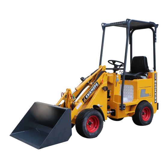
Page 15: Description
Description Description Overview Safety cabin Driver’s seat Inching pedal Counterweights (optional) Parking brake Hydraulic control Steering wheel Engine compartment Dashboard Fuel tank Lifting eyes and tie-down points Hydraulic fluid tank Boom Jib locking pin Mounting plate Seatbelt Accelerator... -
Page 16: Type Plate
Description Type plate The illustrations shows an example of the layout of the type plate on the machine. The actual type plate on the machine shows the correct data depending on the type of machine. Dashboard Ignition key Neutral position indicator Fuse box Engine oil pressure Alternate hydraulic function switch,... -
Page 17: Hydraulic Control
Description Hydraulic control Lever for auxiliary hydraulic function Button for auxiliary function direction 1 left. Lever for boom extension. See Button for auxiliary function direction 2 section 4.4. Horn No function Travel direction button Button for boom extension and retraction. -
Page 18: Mounting Plate
Description Mounting plate Electrical connection for electrical Locking pin levers function Connection for auxiliary hydraulic Locking pins function Mounting plate... -
Page 19: Sticker For Hydraulic Control And Boom Level Functions
Description Sticker for hydraulic control and boom level functions Lower boom Auxiliary hydraulic function Raise boom Extend boom Mounting plate forwards Retract boom Mounting plate backwards Interchangeable accessory hydraulic pressure direction 1 Boom extension function Interchangeable accessory hydraulic pressure direction 2... -
Page 20: Driver's Seat
Description Driver’s seat Lever for adjusting the driver’s seat Knob for adjusting the backrest forwards and backwards Knob for driver weight adjustment Handle for adjusting the backrest angle Operating principle: driving the wheels Hydraulic wheel motors drive the wheels of the machine, one motor per wheel. The hydraulic pressure comes from a hydraulic pump that is driven in turn by a diesel engine. -
Page 21: Daily Use
Daily use Daily use Starting Safety Warning: Do not exceed the maximum loading. For the specifications, see chapter 7. Preparation 1. Make sure that the daily maintenance has been carried out. See section 5.1. 2. Check the fuel level and the hydraulic fluid level. Top up the relevant tank if necessary. a) Topping up the fuel: see section 4.7. -
Page 22: Stop
Daily use Stop 1. Stop the machine on flat ground if possible. 2. Place the boom on the ground, if no load is present, or the place the load on the ground. 3. Pull the parking brake fully up. 4. Put the following controls in the neutral position: a) Driving direction button b) Boom lever... -
Page 23: Driving
Daily use Driving 1. Press the parking brake button and fully lower the parking brake. 2. Choose a driving direction: a) If you want to drive forwards, set the direction button (A) to the forward position (F). b) If you want to drive in reverse, set the direction button (A) to the reverse position (R). -
Page 24: Attaching An Interchangeable Accessory
Daily use Attaching an interchangeable accessory Release the pressure in the hydraulic system for auxiliary functions 1. Turn the ignition key to the ‘OFF’ position to switch off the engine. 2. Move the levers for the auxiliary hydraulic functions back and forth several times to remove the hydraulic pressure. -
Page 25: Detaching An Interchangeable Accessory
Daily use Detaching an interchangeable accessory About this task Caution: When the interchangeable accessory is connected to the hydraulic quick release couplings, first disconnect the auxiliary function connections before disconnecting the interchangeable accessory from the machine. Procedure 1. Place the interchangeable accessory on the ground. -
Page 26: Refueling
Daily use Refueling Before you start The fuel is flammable and can be dangerous. Be careful when handling fuel. Warning: • Use only the right fuel and do not mix it with petrol or alcohol. Such a mixture can damage the engine or cause an explosion, •... -
Page 27: Installing Counterweights
Daily use Installing counterweights Safety Warning: A minimum of two people are needed for lifting the counterweights. Each counterweight weighs more than 30kg. Procedure Installing the first counterweight 1. Remove the bolts (A). 2. Remove the panel (B). 3. Position the counterweight (C). 4. -
Page 28: Mounting And Removing The Jib Lock
Daily use Mounting and removing the jib lock The jib lock is intended to prevent the machine from bending in the event of a failure of the control mechanism. Safety Warning: Make sure the engine is switched off before you perform any actions on the jib lock. -
Page 29: Transport And Storage
Daily use Transport and storage Transport: safety instructions About this task Caution: • Do not tow the machine. • Make sure that the machine is not exposed to external shocks, vibrations and collisions. • Protect the machine against external influences such as rain, splashing (salt) water, dirt and dust. -
Page 30: Maintenance
Maintenance Maintenance Daily maintenance Before you start Warning: Do not touch hot parts of the machine: engine, exhaust and hydraulics. About this task The daily maintenance may be carried out by the machine operator or by someone with an equivalent level of training. Procedure 1. -
Page 31: Maintenance Table: Maintenance With The Machine Switched On
Maintenance Machine part Procedure Rejection criterion Action on rejection Hydraulic fluid Check the level. See Hydraulic fluid level not Adjust the hydraulic fluid level. Procedure: section 5.12. correct. 5.12. see section Parking brake Check the operation. Contact a qualified Correct operation. See section 0. -
Page 32: Periodic Maintenance (Qualified Service Technician)
Maintenance Periodic maintenance (qualified service technician) Warning: Never stand underneath the boom during maintenance. The boom can unintentionally lower during maintenance. The periodic maintenance of the machine must be carried out by a qualified service technician. The table below indicates the frequency at which certain maintenance tasks must be performed. -
Page 33: Opening The Engine Compartment
Maintenance Opening the engine compartment Safety Warning: Do not touch hot engine parts. Procedure 1. Align the lever (A) with the machine. 2. Open the cover, including the driver’s seat (B). Clean the pre-filter The pre-filter is at the back of the machine and is used to filter very coarse dust from the air before it goes to the air filter. -
Page 34: Check The Fan Belt Tension
Maintenance Check the fan belt tension Before you start 1. Open the engine compartment. See section 0. 2. Push the belt (A) with your thumb at the largest span. The belt must have a play of between 1/4” (7 mm) and 3/8”... - Page 35 Maintenance Grease nipple...
-
Page 36: Check/Top Up The Engine Oil Level
Maintenance Check/top up the engine oil level Safety Warning: The oil dipstick is situated close to the exhaust. Make sure the engine is cold before checking the oil level. Procedure 1. Open the engine compartment. See section 0. 2. Remove the engine oil dipstick (A) from the holder, clean the engine oil dipstick and refit it. -
Page 37: Check And Top Up The Hydraulic Fluid Level
Maintenance Topping up 1. Remove the cap (A) from the radiator. First unscrew it 1 turn and allow any overpressure to escape before you completely remove the cap. 2. Fill coolant fluid up to the ‘FULL’ mark on the reservoir. For the correct type of coolant fluid, see section 7.1. -
Page 38: Replace The Air Filter
Maintenance Replace the air filter Spares • For the correct replacement parts, contact the manufacturer. Safety Note: This procedure may only be carried out by a qualified service technician. Remove the cover 1. Open the engine compartment. See section 0. 2. -
Page 39: Replacing The Hydraulic Fluid Filters
Maintenance Replacing the hydraulic fluid filters Spares • For the correct replacement parts, contact the manufacturer. Safety Note: This procedure may only be carried out by a qualified service technician. Replacing the intake filter 1. Remove the side panel (A). 2. - Page 40 Maintenance Grease nipple...
-
Page 41: Troubleshooting
Troubleshooting Troubleshooting Daily maintenance 1. Try to resolve the problem using the troubleshooting table to find a resolution for the problem. 2. If you cannot find a solution to the problem, contact a qualified service technician or the manufacturer. Describe the problem in as much detail as possible and clearly indicate what steps you have already taken before contacting the qualified service technician or the manufacturer. - Page 42 Troubleshooting Problem Possible cause Possible resolution It is not possible to connect The machine is still under Turn the ignition key to the hydraulic connection of pressure. the ‘OFF’ position to the interchangeable switch off the engine. accessory. Move the levers for the hydraulic functions back and forth several times to remove the hydraulic...
-
Page 43: Technical Data
Technical data Technical data Consumables Article Specification Fuel Diesel class EN 590. If in doubt, consult the diesel engine user manual. Check and follow the regulations of the country where you are located. The use of ‘red diesel’ is not allowed in certain countries. -
Page 44: Reference Figure: Dimensions
Technical data Reference figure: dimensions Wheelbase Roll bar height/ROPS-FOPS height Total length without shovel bucket Seat height Total length without shovel bucket Ground clearance Total width Tipping angle from ground surface Width Boom hinge height Maximum steering angle Transfer height Outer turning radius Max attachment system hinge height... -
Page 45: Reference Figure: Maximum Load
Technical data Reference figure: maximum load Fully retracted boom (smallest Fully extended boom (greatest torque) torque) KM100TE Table 1: Dimensions Posi- Parameter Unit Value tion Wheelbase [mm / in] 1530 / 60.24 Total length without bucket [mm / in] 2610 / 102.8 Total length with bucket [mm / in] 3250 / 128... - Page 46 Technical data Table 2: Maximum load Position Status Unit Value 1 (X = 995 mm) Not articulated, telescopic [kg / lbs] 800 / 1763 arm retracted 1 (X = 1800 mm° Not articulated, telescopic [kg / lbs] 400 / 882 arm extended 2 (Y = 1475 mm) Not articulated, telescopic...
Need help?
Do you have a question about the KM80 and is the answer not in the manual?
Questions and answers