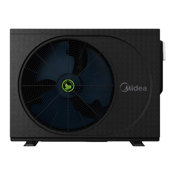
Summarization of Contents
General Information
Lineup
Details the different models and their appearance.
Nomenclature
Explains the model naming convention and component breakdown.
Engineering Data
Specifications
Provides detailed technical specifications for each model, including capacity, input, and COP.
Electrical Characteristics
Details voltage, current, power, and component electrical data for different models.
Dimensions and Center of Gravity
Shows physical dimensions and weight of the heat pump units.
Operating Limits
Defines the operational temperature ranges for heating and cooling modes.
Heating Performance
Presents graphs showing heating capacity and COP versus ambient temperature.
Hydronic Performance
Illustrates the relationship between water flow rate and water pressure drop.
Octave Band Sound Level
Displays sound pressure levels across different frequencies for various sides.
Component Layout and Refrigerant Circuits
Layout of Functional Components
Identifies and illustrates the placement of key internal components.
Piping Diagrams
Shows schematic diagrams of refrigerant flow for heating and cooling modes.
Control
Stop
Explains the conditions and reasons for the unit's stop operation.
Standby
Describes the water pump control behavior during standby mode.
Startup Operation
Details compressor startup procedures and platform based on ambient temperature.
Normal Operation
Outlines control logic for heating and cooling modes, including component functions.
Special Control
Covers specific operations like oil return, defrosting, and smart grid functions.
Diagnosis and Troubleshooting
Electric Wiring Diagram
Provides a detailed schematic of the unit's electrical connections and DIP switch settings.
Electric Control Box Layout
Illustrates the arrangement of PCBs and other electronic components within the control box.
PCB
Lists and describes the various ports and their functions on the main control board.
Error Code Table
A comprehensive list of error codes and their corresponding malfunctions or protections.
Troubleshooting
Guides users through diagnosing and resolving common error codes and issues.
Temperature Sensor Resistance Characteristics
Provides tables of resistance values for temperature sensors at various temperatures.
USB Function
Explains how to use the USB port for parameter settings and program updates.
Parts Replacement
Wired Controller
Instructions for removing and installing the wired controller.
Flow Switch
Procedures for removing and installing the flow switch.
Compressor
Step-by-step guide for removing and installing the compressor unit.
Titanium Heat Exchanger
Instructions for removing and installing the titanium heat exchanger.
Inverter Module PCB
Detailed steps for replacing the inverter module printed circuit board.


Need help?
Do you have a question about the MSC-120D2N8-A and is the answer not in the manual?
Questions and answers