Table of Contents
Advertisement
Quick Links
Advertisement
Table of Contents

Summary of Contents for Midea MCCU-03CN1A
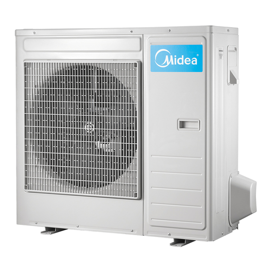
- Page 1 INSTALLATION MANUAL COMPRESSOR CONDENSING UNIT MCCU-03CN1A MCCU-05CN1A MCCU-07CN1A MCCU-10CN1 MCCU-12CN1 MCCU-16CN1 Thank you very much for purchasing our air conditioner, Before using your air conditioner, please read this manual carefully and keep it for future reference.
-
Page 3: Table Of Contents
The appliance must be positioned so that the plug is The appliance must be positioned so that the plug is accessible. accessible. CONTENTS CONTENTS The enclosure of the appliance shall be marked by word, or The enclosure of the appliance shall be marked by word, or by symbols, with the direction of the fluid flow. -
Page 4: Outdoor Unit Installation
2 OUTDOOR UNIT INSTALLATION 2 OUTDOOR UNIT INSTALLATION 2.2 Figure of body size 2.1 Installation Place 2.1 Installation Place The outdoor unit should be installed in the location that The outdoor unit should be installed in the location that meets the following requiements: meets the following requiements: There is enough room for installation and maintenance. -
Page 5: Install The Connecting Pipe
3 INSTALL THE CONNECTING PIPE Table 2-1 MODEL REMARK 3.1 Preparation and Caution Fig.2-2 Before installation make sure the height difference, the length of refrigerant pipe, and the number of the bends 05~07 Fig.2-2 between the indoor unit and outdoor unit meet the following requirements: Fig.2-3 Table 3-1... -
Page 6: Refrigerant Pipe
Be sure to use two wrenches simultaneously when you Table 4-1 Size of joint pipes for 410A outdoor unit connect or disconnect the pipes. the size of main pipe(mm) Model Make the ends straight Gas side Liquid side 03/05 Φ12.7/0.501in Φ6.35/0.25in Fig 3.3 Φ12.7/0.501in... -
Page 7: Heat Insulation Of The Pipe
CAUTION Flare nut Too large torque will harm the bellmouthing and too small will cause leakage. Please determine the torque according to Stopper Table 5-1. Table 5-1 Flare dimensin A Tightening torque Pipe gauge Flare shape (mm) Valve body 14.2~17.2 N.m Ø6.35/0.25in 8.3/0.327in 8.7/0.343in Valve stern... -
Page 8: Connective Diagram
6.2 Heat Insulation Of The Refrigerant Pipe 8 WIRING The appliance shall be installed in accordance with Please use heat-resistant materials as heat insulation materials national wiring regulations. of the air-side pipe. (e.g., EPT) The air conditioner should use separate power supply with rated voltage. -
Page 9: Electric Connection
10 ELECTRIC WIRE DIAGRAM The appliance shall be installed in accordance with national wiring regulations. Power supply: 220-240V~ 50Hz 3-cord cable Specifications of power supply RVV-300/500 2X2.5+1x1.5 mm (MCCU-03CN1A) RVV-300/500 2X4.0+1x2.5 mm (MCCU-05CN1A) Switch capacity Connective Outdoor unit power Model Power... -
Page 10: Trial Run
Air flow of the indoor unit on the electric control box. Table 11-2 Air flow of the indoor unit Model CAUTION MCCU-03CN1A 500~650m Perform the trial run only after the outdoor unit has been MCCU-05CN1A 700~900m powered on for over 12 hours. - Page 12 16123000A18669 V1.0...
- Page 13 本页不打印 规格:A4 材质:100g双胶纸 更改记录...


Need help?
Do you have a question about the MCCU-03CN1A and is the answer not in the manual?
Questions and answers