Table of Contents
Advertisement
Quick Links
Advertisement
Table of Contents

Related Manuals for Hornby HM7000-21TXS


Summary of Contents for Hornby HM7000-21TXS
- Page 1 KW/CR Version 1.0 060323...
-
Page 2: Table Of Contents
HM7000 BLE Decoder… modes of Operation: DCC, Bluetooth or even DC analogue!? Summary Bluetooth advantages… We do not recommend DC operation … Why? DC Power: BLE Only operation Only... notes re Fixed Output DC Power Supplies. Suitable Hornby Power Supplies. R7337 P9100W R7324 P9000 WARNING…... - Page 3 DC Power: BLE Only operation Only... notes re Analogue “Train Controllers” set to maximum output: Special Note: Using HM6000 Circuit Outputs for BLE. DC-Controllers not recommended. HM7000 Decoders… the basic features… an outline. HM7000… Meet the Family… (please note all current pictures are pre-production... they will be updated later.) Sound Decoder Types and Connection 21 Pin BLE Decoder ...
- Page 4 APROM … the Control Code SPIROM … the Sound Code etc Firmware Version Numbers Decoder Updates and firmware structure… Non-Sound Decoders HM7000 Bluetooth Mesh operations … System Overview The Common CVs… General Description CV1… Primary Address CV2… Vstart CV3… Acceleration Rate CV4…...
- Page 5 bit6 … Reserved… bit7 … decoder type select… CV47, CV48 and CV49… Control Processor Firmware Version… APROM CV51 to CV58… Lighting Configuration description… General Description Summary… Hi-Level Outputs ... Summary… Logic-Level Outputs Setting Lighting Effects and Brightness… CV59 to CV66… Auto Function Control (AFC) CV67 to CV94…...
- Page 6 CV159… Volume of F0 (re Sound Only Projects… Does Not Apply to Locomotive decoders.) CV160... ELECTRIC motors volume CV161… Steam/Diesel engine volume on Acceleration and Deceleration CV162 to CV180… Set individual volumes of Spot Sounds F2 to F20 CV200 to CV203… Sound IDs and Versions… SPIROM Horn and Whistle Selection re F2 and F3…...
- Page 7 Appendix 2: How Decoder addressing works… Definitions... General Description... Address selection… Long or Short? How a Short Address is stored… How a Long Address is stored… Hexadecimal?!?!?! Long Address Example… The default addresses set in the decoder are… Short Address… Long Address…...
- Page 8 LEDs… Web further references… Load type… Filament Bulbs/Incandescent lamps etc. … The Last Word… Resistors and power dissipation. IMPORTANT Load Type… RELAYS Example of typical DPDT relay… Relays and Fly Back Diodes!!!! IMPORTANT Fly Back… What’s going on?!? Appendix 4: Setting up Asymmetrical DCC Control… (ADCC) ADCC Explanation CV27…...
- Page 9 So… what’s PID Motor Control Algorithm… how does it work? Proportional… CV153 Integral… CV154 Derivative… CV155 Appendix 7: Power Bank… Hornby “Stay Alive” Connection and Implementation Smart Charging… Appendix 8: Complete CV list for all decoders. Appendix 9: Decoder Operational, Electrical and Physical Specifications Sound Decoders specification.
-
Page 10: Sound Decoders
Operational mode is also supported. By changing CV12 to the value 2, you now have switched control to Bluetooth operation. However, you will require the Hornby HM7000 APP for your mobile device in order to take control….. you will now need the APP!! If you do not have the APP…... -
Page 11: Setup App Procedure
You will be required to login to the APP using your Hornby account. If you do not have a Hornby account press the “Register New Account” button to be taken to the Hornby website. Create an account and wait for the verification email. -
Page 12: Download And Install The Desired Sound Profile
Note: If you scroll down the Locomotive “Settings” page you will find other aspects of the decoder that you can preset. e.g., Acceleration/Deceleration/Global Sound Volume, Import/Export Function Set up and most importantly Locomotive Profiles. There is a browse “Profiles” button. Download and install the desired Sound Profile. -
Page 13: About This Reference Manual
About this reference manual... Scope… This manual is designed to be “universal” i.e., Configuration Variables (CV) listings are universal and cover all decoders in the system. We have indicated where a CV only applies to a particular type of locomotive... i.e., Steam, Diesel, Electric, Electro-Diesel, Non-Sound... etc. The structure of the manual is split into sections dealing with the common CVs of all decoders with other sections dedicated to different sound loco types i.e., electric, steam, diesel etc…... -
Page 14: Hm7000 Series Decoders
The decoder may be controlled/programmed by either DCC NMRA signals received via the track in the conventional way, or by Bluetooth signals transmitted from an IOS or Android Phone/Tablet running the Hornby HM7000 train control APP. The APP can be downloaded for free from the Apple Store or from the Google Play Store. -
Page 15: Bluetooth Advantages
Bluetooth advantages… Using the BLE APP for control has many advantages over the conventional DCC control system. i.e., CV changes and readback are almost instantaneous and there is no need to put the locomotive on a “Service/Programming” track for readback support. The decoder also supports conventional manipulation of CV values i.e., DCC programming operation via a conventional DCC controller. -
Page 16: Dc Power: Ble Only Operation Only
… As suppled with R7229/R8250 Analogue Controllers... These power supplies utilise a different size plug arrangement from the ELITE/SELECT power supplies above. An adapter cable is available (R7403) to suit the P9000W power supply. If Hornby are delayed in offering the R7403 adapter for the P9000W power supply… you can alternatively search eBay for CCTV power adapters/extenders. -
Page 17: Dc Power: Ble Only Operation Only
Please use the power supply that came supplied with the HM6000 unit directly connected to the track and remove the HM6000. DC-Controllers not recommended. HM2000 The Hornby HM2000 analogue controller does not work well… sound distortion 100Hz modulations? R7229/R8250 These controllers use a low frequency PWM system that can cause issues with decoder control etc. -
Page 18: Hm7000 Decoders
HM7000 Decoders… the basic features… an outline. Note some features listed are not supported in all decoders… as indicated. ● Full Bluetooth wireless control via APP based control interface. ● Full CV programming and Read-back via APP interface. ● Full Support of DCC operations. ●... - Page 19 ● OTA update support. This feature supports decoder code updates via Blue Tooth and the possibility of changing the decoder “sound set” on sound decoders is supported... Different loco types “sound sets” are available for free download from the Hornby web-site via the APP.
-
Page 20: Hm7000
“Pack.” Part number R7377… see Appendix 7: Power Bank… Hornby “Stay Alive” Connection and Implementation HM7000 series sound decoders all have provision for connecting a loudspeaker on the decoder pcb in the form of solder pads and a two-pin socket. Loudspeaker connections are also presented through the decoder main connector on the locomotive main PCB via solder pads and a socket where applicable. -
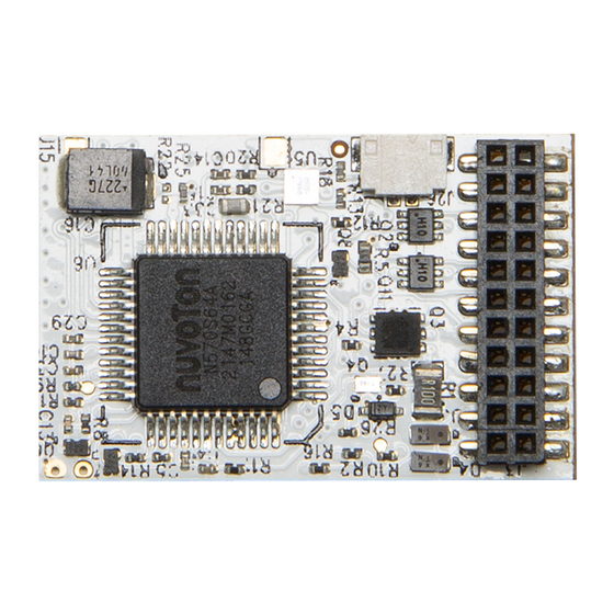
Page 21: Sound Decoder Types And Connection
Sound Decoder Types and Connection 21 Pin BLE Decoder ... HM7000-21TXS ... R7322……………………. Dimensions 15.5mm x 29.5mm x 4.9mm Termination 21MTC KBW/CR Version R1.0 140323 Take me back to Top…. Page 21 of 130... - Page 22 Pin # Name Function Colour AUX7 Logic output/input HFO9d… Controlled by BLE MCU AUX8 Logic output/input HFO10d… Controlled by BLE MCU AUX 6 Logic output/input HFO8d… Controlled by BLE MCU AUX 4 Logic output/input HFO6d… Controlled by BLE MCU No Connection ZBDATA/AUX10 SWS Prog/Debug of BLE MCU …...
-
Page 23: Pin Ble Decoder
8 Pin BLE Decoder ... HM7000-8TXS ... R7336…… Dimensions 14mm x 28.5mm x 4.9mm Termination NEM 652 8 pin + flying lead Pin # Name Function Colour KBW/CR Version R1.0 140323 Take me back to Top…. Page 23 of 130... - Page 24 MTR + Motor Right/Positive Orange 2 F0r HFO2… Yellow 3 AUX1 HFO3… Green 4 Power Left Rail pickup Black 5 MTR - Motor Left/negative Grey 6 F0f HFO1… White Decoder Positive (HFO Common) Blue 8 Power Right Rail pickup Flying wire AUX2 HFO4…...
-
Page 25: Next 18-S Pin Ble Decoder
Next 18-S Pin BLE Decoder ... HM7000-N18TXS ... R7345………. Dimensions 14mm x 28.5mm x 4.9mm Termination Next18-S Name Description KBW/CR Version R1.0 140323 Take me back to Top…. Page 25 of 130... - Page 26 1 Power Right Rail Pickup Common with pin18 2 MTR + Motor Right/Positive 3 AUX1 HFO3… AUX3 HFO5d… Digital Output… Controlled by BLE MCU 5 Ground - Decoder Ground, tapped at internal rectifier. Common with pin14 6 V+ Decoder Positive (HFO Common) Electrically Common with pin15 7 LS/B Loudspeaker 8 F0f...
-
Page 27: Non-Sound Decoder Types And Connection
Non-Sound Decoder Types and Connection Non-Sound Decoders… Operational limitations – Notes Non-Sound decoder types have a different processor architecture from the Sound decoder types. This means that some features are not supported, and other features require different operational procedure. Non-Sound Decoders do not at this time support ABC i.e., ADCC operation (See ABC- ADCC later in this manual.) The decoder selects Bluetooth or DCC depending on track power type. -
Page 28: Pin Ble Decoder
8 Pin BLE Decoder ... HM7000-8 ... R7335…………. Dimensions 8mm x 21.5mm x4 mm Termination NEM 652 8 pin KBW/CR Version R1.0 140323 Take me back to Top…. Page 28 of 130... - Page 29 Pin # Name Function Colour MTR + Motor Right/Positive Orange 2 F0r HFO2… Yellow 3 AUX1 HFO3… Green 4 Power Left Rail pickup Black 5 MTR - Motor Left/negative Grey 6 F0f HFO1… White Decoder Positive (HFO Common) Blue 8 Power Right Rail pickup View looking down at the locomotive decoder socket Pin 1 may be designated by a star, a square or spot printed on the locomotive pcb.
-
Page 30: Pin Ble Decoder
6 Pin BLE Decoder ... HM7000-6 ... R7321……. Dimensions 8mm x 22.5mm*** x 4mm *** including pin length, pcb length is 17mm Termination NEM651n 6 pin KBW/CR Version R1.0 140323 Take me back to Top…. Page 30 of 130... - Page 31 This type of connection is made up of pins on the decoder and a socket fitted on the loco pcb. Note: If the locomotive has a socket with a wiring harness it should use the wire colours correspond to the table below. Pin # Name Function Colour...
- Page 32 No information is currently available re…. HM7000-18 R7401 … Next18 Non-Sound Decoder HM7000-21 R7402 … 21pin Non-Sound Decoder KBW/CR Version R1.0 140323 Take me back to Top…. Page 32 of 130...
-
Page 33: Decoder Function Lists And Function Description
Please check your locomotive sound profile documentation for full details of the sounds available and F# mapping for your locomotive/decoder sound profile. Function lists for each profile will be available for download from the Hornby website. When you download a locomotive sound profile. On installation, part of the process will configure the APP Control Screen for that locomotive. i.e., it will show the appropriate buttons and icons for the specific functions/sounds for your locomotive. -
Page 34: Electro-Diesel Sound Decoders
Electro-Diesel Sound Decoders… Features and Functions The function allocated to each F# is fixed. Remapping of Function numbers is not supported. F0... Directional Lighting (HFO1 and HFO2) – (if installed.) F1... Engine running sounds enable. F2… Horns play. Different horns will be played on each press of the F# on the controller. Horns are selected sequentially or randomly. Configurable by CV. F3…... - Page 35 F26… Activate “Creep Mode” … Coupling assistance. Creep speed and duration are configurable by CVs. F27… Apply Brake action (overrides current deceleration level.) Brake deceleration rate is configurable by CV. F28… Enables Automatic Spot Sound Play. Choice of spot sounds is configurable by CVs. KBW/CR Version R1.0 140323...
-
Page 36: Diesel Sound Decoders
Diesel Sound Decoders… Features and Functions F0... Directional Lighting (HFO1 and HFO2) – (if installed.) F1... Engine running sounds enable. F2… Horns play. Different horns will be played on each press of the F# on the controller. Horns are selected sequentially or randomly. Configurable by CV. F3…... - Page 37 F27… Apply Brake action (overrides current deceleration level.) Brake deceleration rate is configurable by CV. F28… Enables Automatic Spot Sound Play. Choice of spot sounds is configurable by CVs. KBW/CR Version R1.0 140323 Take me back to Top…. Page 37 of 130...
-
Page 38: Electric Sound Decoders
Electric Sound Decoders… Features and Functions F0... Directional Lighting (HFO1 and HFO2) – (if installed.) F1... Engine running sounds enable. F2… Horns play. Different horns will be played on each press of the F# on the controller. Horns are selected sequentially or randomly. Configurable by CV. F3…... -
Page 39: Steam Sound Decoders
Steam Sound Decoders… Features and Functions F0... Directional Lighting (HFO1 and HFO2) – (if installed) F1... Engine background steam and running sounds enable. F2… Whistle play. Different whistles will be played on each press of the F# on the controller. Whistles are selected sequentially or randomly. Configurable by CV. F3…... -
Page 40: Non-Sound Decoders
Non-Sound Decoders… Features and Functions Non-sound decoders currently support 6 functions. See below. The function allocated to each F# is fixed. Remapping of Function numbers is not supported. Only 3 HFO connections are available… i.e HFO1 – HFO3 F0… Headlight/Rear light… HFO1 and HFO2 – (if installed.) F1…... -
Page 41: Decoder Firmware Description, User Updates, Sound Profiles, And Getting Help
“BLE Communications” BLE is used for control/programming/update of the decoders. OTA updates All decoders can be updated “over the air” (OTA.) by using the Hornby HM7000 APP. i.e. The APP has built in support for downloading and carrying out the OTA update. Updates consist of…... -
Page 42: Decoder Updates And Firmware Structure
Decoder Updates and firmware structure… Sound Decoders Structure Notes… and updates A full description of the internal structure and operation of the decoder is outside the remit of this manual. However, the Sound Downloads from the HM7000 web site will be referred to as the “Sound Profile”... -
Page 43: Firmware Version Numbers
Within the APP the “Device Versions” screen refers to the LDROM, APROM and SPIROM differently…. BOOT ROM… i.e., the LDROM Boot code PROFILE ROM… this the APROM and SPIROM combined. This was done to simplify the user experience when talking to customer care etc when referring to the APP. Firmware Version Numbers The decoder itself holds the full break down of the SPIROM and APROM version numbers using CVs if more detailed information is required... -
Page 44: Hm7000 Bluetooth Mesh Operations
HM7000 Bluetooth Mesh operations … System Overview The HM7000 “ecosystem” utilises Bluetooth communications. Originally, Bluetooth was designed to offer a wireless alternative to USB. USB was designed to connect many peripherals to a central PC etc. The HM7000 utilises a more recent variant of Bluetooth called “Bluetooth Mesh.” Bluetooth Mesh allows many Bluetooth devices to talk to each other thus forming a cross connected network that passes data around. -
Page 45: The Common Cvs
May contain an address with a value between 1 and 127. Note some controllers may store addresses 100-127 in this location. Note some controllers maybe restricted to less that 127 e.g., Hornby SELECT – Locomotive address rage 1-59. Default Value... -
Page 46: Cv3
CV3… Acceleration Rate Determines the decoder's acceleration rate. The acceleration rate change per increment in CV value is determined according to a formula issued by the NMRA. Please check the NMRA web site for a full description. If the content of this parameter equals "0" then there is no programmed momentum during acceleration. (i.e., there will be no throttle lag.) Default Value Range 0-255... -
Page 47: Cv6
Comments For readback test only CV8… Manufacturers ID and RESET decoder. Each manufacturer of DCC equipment etc has a specific ID allocated by the NMRA. Range not specified… Default is 48 indicating “Hornby.” Default Value Range Comments Values assigned by NMRA Special RESET functionality: By writing the value 8 to this CV it is possible to reset all CVs of the decoder. -
Page 48: Cv10
CV10… Back-EMF Feedback Cut-out Speed Step The decoder supports BEMF monitoring for maintaining a constant speed with varying load. i.e., this could apply to the locomotive negotiating curves and inclines etc. This CV allows the user to pre-set the point where BEMF compensation ceases to be supported dependent on a Speed Step value. Default Value Range 1-127... -
Page 49: Cv17 And Cv18
CV17 and CV18… Storing Long Addresses CV17 and CV18 are used to store “Long Addresses.” There are two CVs involved i.e., 2 bytes of information. A long address is generally any address above 127. However, some decoder will store addresses above 99 in these CVs. This will depend on the controller in use. To the user the process is transparent…... -
Page 50: Cv27
CV27… Asymmetric DCC (ADCC) Configuration… (ABC operation) … rail select. Originally invented by Lenz, Asymmetrical DCC Control facilitates a simple way of creating basic locomotive automation on your layout. Sometimes this feature is referred to as Automatic Brake Control (ABC.) ADCC/ABC operation can be used to stop a loco automatically, reverse a loco or other actions without any input from the user on the DCC control system i.e., decoders with an ADCC function can be programmed to carry out a range of automatic actions. -
Page 51: Cv29
CV29… Decoder Configuration … general explanation This CV is used to set up how some of the decoder features work. e.g., loco default direction, which speed table to use etc… see below for full list. Default Value Range 1-255 The CV stores a simple binary number, i.e., a string of “ones and zeros.” The stored binary number is usually referred to in its Decimal form for simplicity. The position of each “one or zero”... -
Page 52: Cv29
Explanation… Loco decoders usually by default can operate under DC control on an analogue layout. However, on the Hornby HM7000 series decoders, you can disable this feature by changing this bit. If a decoder fitted locomotive is not going to be run on any analogue layout Hornby recommends that the parameter is set to “DCC Only”. -
Page 53: Bit3
Explanation… Some decoders support RailCom®. This is a feature which enables a decoder’s CVs to be read back while the locomotive is on the Main Track. i.e., this applies to DCC operation only. This decoder supports BLE communications and decoder configuration can be readback via the Hornby BLE APP. -
Page 54: Bit5
bit5 … Address Selection… “short” or “long” address mode … EQD = 32 Explanation… Most decoders can store a long and a short address simultaneously. This CV sets which address is used (i.e., in play.) Detail… Short addresses are usually 1-127 are stored in CV1, long addresses 1-9999 are stored in CV17 and CV18 i.e., they work together to store the “long address.” bit5 is disabled by default. - Page 55 CV47, CV48 and CV49… Control Processor Firmware Version… APROM Decoder APROM firmware release information is stored here… the decoder can be updated over the air (OTA.) We use these CVs to keep track of the current version of firmware currently loaded. Control Processor Firmware Version (CV47-49) The format of the software version of the decoder is: "v [Major#] [Minor#] [Patch#]"...
-
Page 56: Cv51 To Cv58
CV51 to CV58… Lighting Configuration description… General Description Generally, all lighting used in a modern locomotive will be LED types. However, other types of load can be connected… see notes in Appendix 3: Using AUX Outputs… i.e. the Hardware Function Outputs… (HFOs) re connecting various other types of load to the HFOs. -
Page 57: Setting Lighting Effects And Brightness
Setting Lighting Effects and Brightness… Warning… HFOs can also be utilised for loco features other than lighting. When connected to non-lighting features the following CV information may or may not apply. This depends on the nature of the feature to be controlled. However, some “effect” modes listed below may have use with other types of connected peripheral devices. HFO1, HFO2, HFO3 and HFO4…... -
Page 58: Cv59 To Cv66
CV59 to CV66… Auto Function Control (AFC) The decoder can be configured to play a random spot sound at a random/sequential interval between 25 and 36 seconds... Two different sets of Spot Sounds can be configured for play depending on whether the locomotive is stationary or on the move. The only limit to the number of spot sounds that can be selected in each mode will depend on the sounds available for the particular locomotive sound profile you have loaded. -
Page 59: Cv67 To Cv94
CV67 to CV94… Speed Table Configuration This range of CVs allow the user to configure the “throttle” response of the locomotive/decoder. The table of values describe a “Speed Curve.” For a more complete description of “Speed Tables” … See… for Appendix 6: All about Motor Control and Tuning... -
Page 60: Special Decoder Functions
Special Decoder Functions… F25/28 Sound Decoders … F5/F8 Non-Sound Decoders... configured by CV120 to CV124 General Description The HM7000 decoder has several special features that are enabled via Function numbers on the controller. Each the action of each of these “special functions” may be configured with its own dedicated CV range. Special Function F# Sound Decoders F# Non-Sound Decoders... -
Page 61: F26
F26… “Creep” mode… Coupling Assist CV121-122 The loco can be set to “creep” forwards or backwards at a pre-set speed. This feature is designed to assist when coupling or carrying other shunting operations. The direction of “creep” will depend on the last selected direction. On activation of F26, the locomotive will “creep” for a preset period of time… This is a momentary function on the controller. -
Page 62: F27
F27… Manual Application of Brake during normal deceleration… CV123 When the loco is decelerating extra brake effort may be applied. CV4 is used to set up a deceleration level for normal use. CV123 allows you to set a secondary deceleration level to simulate locomotive braking. -
Page 63: F28
F28… Enable/Disable Auto Function Control (AFC) of Spot Sound Play … CV59 – CV66 The sound decoders can be configured to play a random spot sound at a random interval between 25 and 36 seconds... When “Auto Function Control” (AFC) is enabled, the decoder will automatically play a horn/whistle sound as the locomotive moves off. The horn/whistle played is from the group of whistles/horns associated with F2 as configured in CV205 …... -
Page 64: Programming Explanations
Programming explanations… CV59 selects whether sounds are played in sequential or random order while the loco motive is running. CV63 selects whether sounds are played in sequential or random order while the locomotive is stationary. Sound Selection... help… By setting the bit representations of the sound in each of the CVs listed in the table, it is possible to select which sounds you want to play during AFC operation. Note: these sounds are additional to the automatic sounds played as the locomotive starts to move or comes to a halt. -
Page 65: Working Out Cv Values To Enable Specific Sounds
Working out CV values to enable specific sounds… From the tables above it is possible to calculate the Decimal value required to be entered in a CV to select specific sounds for play. 1, Select the sound you desire 2, Ignore the Bit# column and look at the number shown in the ADD column. Remember this number. Keep repeating this process until you have a string of numbers that represent the sounds you wish to play during AFC operation. -
Page 66: This Feature Applies Only To Non-Sound Decoders
F8… “Push Button” operation, set speed… CV??? This feature applies only to non-sound decoders. This feature is in development…. By enabling F8 on the controller the decoder motor output will accelerate and then hold a pre-set speed. On disable the motor will decelerate and stop. Primarily aimed for when the decoder is used for simple motor control scenarios e.g., motor driven trackside accessories etc. -
Page 67: Sound Decoders
We have set the default volume level for each locomotive type to a value which will suit most environments. In practice due to the vast range of speaker types that get used with decoders (including Hornby speaker types) we have decided that setting a lower default volume rather than mid-way was prudent. -
Page 68: Cv159
CV159… Volume of F0 (re Sound Only Projects… Does Not Apply to Locomotive decoders.) This CV only applies to specialised sound only type decoders i.e, it, does not apply to locomotive control decoders. Note that “sound only decoders” use the same basic hardware as the locomotive types. -
Page 69: Cv162 To Cv180
Each sound decoder sound set is tailored for a particular locomotive, and therefore may well be differ in spot sound content between specific locomotives. When you download a locomotive sound set from the Hornby website you will be provided with a QuickStart guide for that locomotive download i.e., it will list the actual sounds implemented re the locomotive…... - Page 70 CV200 to CV203… Sound IDs and Versions… SPIROM General Description… Decoder sound firmware release information is stored here… the decoder can be updated over the air (OTA.) We use these CVs to keep track of the current version of sound firmware currently loaded. Default does not apply...
-
Page 71: Horn And Whistle Selection Re F2 And F3
Each of these two F numbers can have up to 8 different horns/whistles etc associated with it. Full function listings are available for each “Sound Profile” from the Hornby website. These “profiles” contain a full list of all the whistles available re F2 and F3. -
Page 72: Programming Tips
Referring to the table below... Select the desired whistle/horns and add the number in the ADD column to arrive at simple Decimal value to programme the CV with. Please download the specific “Function List” for your sound profile from the Hornby Web-site. This will give a full list of all Horns/Whistles available for use with F2 and F3. -
Page 73: Diesel Locomotives Engine Running Sound Playback
DIESEL LOCOMOTIVES Engine Running Sound Playback… 3 Notch and 4 Notch Systems. Earlier/Original released TTS diesel locos were designed with a 3 notch + Idle engine sound system. The configuration of this system only differs from the full 4 notch + Idle system employed on later TTS projects by the addition 2 extra CVs for the parameters controlling transition from the 3 notch to the 4 notch and back again. -
Page 74: Diesel Sound
Diesel Sound… How it works… 3 or 4 notches... Detail… For this explanation we are assuming a 4 Notch system... see above for explanation of the difference between 3 Notch and 4 Notch Systems. When the locomotive is stationary Diesel Idle sounds are played. To add further “realism”... -
Page 75: Diesel
Diesel… Examples of operation Acceleration . Here are some examples of how the system responds using the default settings set out in the table above... 1. You turn the throttle up to just get the locomotive moving. The speed step applied is less than 5. Decoder plays the following sequence of engine sounds... -
Page 76: Cv225
5. You turn the throttle up from zero to speed step 66 Decoder plays the following sequence of engine sounds... IDLE – Transition to NOTCH 1 – Transition to NOTCH 2 – NOTCH 3 – Remains at NOTCH 3 Note: When the locomotive moves off, brake release sounds are played automatically. Deceleration So far, we have talked about acceleration, deceleration follows different rules. - Page 77 KBW/CR Version R1.0 140323 Take me back to Top…. Page 77 of 130...
-
Page 78: Electric Locomotives
ELECTRIC LOCOMOTIVES… Engine Running Sound Playback… Explanation and Configuration… CV218 to CV222 The system of operation is similar to the Diesel system described earlier. The decoder in your locomotive is designed to operate at 5 different rev levels… i.e., Notches. Each rev level above “IDLE”... - Page 79 KBW/CR Version R1.0 140323 Take me back to Top…. Page 79 of 130...
-
Page 80: Electro-Diesel Locomotives
ELECTRO-DIESEL LOCOMOTIVES… Engine Running Sound Playback… Explanation and Configuration… CV210 to CV222 General Description… This type of locomotive has the ability of running on either electric or diesel engines. It can swap between engine types when running. i.e., the decoder sound system can playback either electric or diesel sounds and transition between them as desired. The playback/operation and configuration of each motor type i.e., diesel or electric is as per the single engine types. -
Page 81: Steam Locomotives
How it works… more detail. Each DIESEL notch has a “fast” run down and Off sound corresponding to each of the “4 notches” available in DIESEL mode. Conversely, there are 4 “fast” DIESEL “start and run up” sound corresponding to each of the 4 notches. ELECTRIC works in a similar way…... - Page 82 When F1 is enabled background steam sounds are played e.g., the hiss of the boiler etc. Chuff rate is controlled by Speed Step value. The controller sends Speed Step values between 0 and 127 to the decoder. This is the target speed of the locomotive... The decoder actually applies acceleration/deceleration to this speed step value, thus controlling the rate of acceleration/deceleration.
-
Page 83: Automatic Wheel Slip Behaviour Simulation
Automatic Wheel slip behaviour simulation … CV213 and CV216 In default operation pressing F6 will activate a “wheel slip” sound. (This is “manual mode”) Wheel slip can be initiated automatically by configuring CV213 = 1... Automatic Wheel Slip enable. In Auto mode, wheel slip sounds will be activated if the amount of throttle increase is greater than the “overshoot value” set by CV214. During a “Wheel Slip” event while in automatic mode the speed of the locomotive will not increase. -
Page 84: Appendix 1: Cvs
Appendix 1: CVs... what are they?? What do they do? And dealing with binary, if you really want too… A Locomotive decoder is a complex device whose main purpose is to control the locomotives motor and other functionality (e.g., lighting etc.) How the decoder controls these features is configurable. -
Page 85: Convert A Decimal Number To Binary
Convert a Decimal number to binary… Explanation: each “bit position” 0 – 7 represents a Decimal value. see table below. OK, try this… How to store any Decimal value as a binary number… this isn’t as bad as it looks... once you have worked through an example it will be clear what s going on. Think of a number between 0 and 255. -
Page 86: Convert A Binary Number To Decimal
Convert a binary number to Decimal? If you have been through the example above, converting between binary to Decimal numbers should be clear. Write the binary number down. i.e., as it appears. Starting at the most right-hand digit, i.e., this will be bit0, moving from right to left follow this rule… Looking at the table above you will see each bit position has a an equivalent Decimal value…... -
Page 87: Definitions
4 digit displays. E.g., the ELITE. Other controllers may limit at a lower value…e.g., Digitrax Zephyr at 9983 It should be noted that some controllers e.g., the Hornby Select will artificially cap the highest address allocatable to a decoder. (The Selects will only allow locomotive addresses between 1-59.) -
Page 88: Address Selection
Address selection… Long or Short? Due to the above, it can be seen that a decoder contains two different addresses. CV29 is used to select which address the decoder internally uses as its active ID address. If CV29 bit5 is set to “off” will mean that CV1 as the active address. Clearly, if bit5 to “on” the decoder will use the long address stored in C17 and CV18 as the decoder ID address. -
Page 89: Long Address Example
Long Address Example… Using a Long Address 9999 as an example… 1, The Decimal value is converted into a hexadecimal value... e.g., 9999 becomes 270F 2, The hexadecimal value is split into two components... the most significant byte (msb) i.e., 27, and the least significant byte (lsb) i.e., 0F 3, The hexadecimal values MSB and LSB are then converted into binary numbers to be stored in CV17/18... -
Page 90: Controllers Old And New And Programming Addresses
Controllers old and new and programming Addresses. A decoder can hold two different addresses simultaneously i.e., a “short address” and a “long address.” Since the way these two types of addresses are stored in the CV range there are two different approaches to carrying out the actual programming process… see above. Older controllers…... -
Page 91: Introduction
Appendix 3: Using AUX Outputs… i.e., the Hardware Function Outputs… (HFOs) Introduction… Please check the table below to understand how the naming conventions relate to each other. For some practices it easier to refer to an HFO when talking about the electrical connection. -
Page 92: The Hardware Function Outputs
The Hardware Function Outputs… HFO … electrical information. There are two types of HFO. Analogue High-level switches… HFO1 to HFO4… FO, F1 and F3…. HFO3 = F1 HFO4 = F2 You can think of the first 4 HFOs (i.e., HFO1 to HFO4) actually consist of transistor negative going switches. Typically, a LED will be connected with its associated series resistor to one of the HFO, the other LED connection will be to the common positive of the decoder. -
Page 93: Connecting Leds To 8 Pin, 21 Pi And Nex18 Decoders
Load Type… LEDs Connecting LEDS to 8 pin, 21 pi and Nex18 decoders. These types of decoders have a common positive bus available on the plug/socket. This common positive bus will be used to terminate LEDs within the locomotive. Each LED has a switched negative connection i.e., HFO. -
Page 94: Connecting Leds To 6 Pin Decoders
Connecting LEDS to 6 pin decoders. Unlike other decoders there is no positive bus connection for the LEDS available on the decoder plug/socket. The only LED connections supplied on the decoder plug socket are the switched negatives (HFOs) for the Reverse/Forward lighting arrangement. i.e., HFO1 and HFO2. Clearly the LED lighting arrangement requires a common positive connection. - Page 95 Explanation… As in the example above, the LED has to be connected to an alternative +ve voltage source. i.e the rails The LEDs is connected to both rails (via the pickups) using a pair of diodes (“Pick Up Diodes”) within the locomotive. The signal on the rails is effectively AC, the common +ve is available for both halves of the AC waveform, alternating between the rails at high frequency.
-
Page 96: Led Current Draw
LED Current Draw… It is usual to run LEDs at a current of between 10 and 20mA for general purposes. While lower or higher currents may be desired for some types of LED than the 10 to 20mA range, for our purposes in these notes we will consider the 10 to 20mA current levels as they more commonly used in model railway applications. -
Page 97: Bi-Colour Led Types
Bi-Colour LED Types… Generally, the types of LED you will use will be single LED packages. However, there are packages used that have two different colour LEDs within the same package. These can be useful in coloured signals etc. If using this type of LED, it is important that it is a “common anode” type. See the diagrams below. For a full explanation see above. These diagrams generally represent how multiple LEDs would be connected to the decoder. -
Page 98: Led Types And Sizes
LED types and sizes… Physically, LEDs come in to two main types… Through Hole (TH) mounting and Surface Mounting Devices... (SMD.) TH LEDs are designed to be mounted on a printed circuit board with connection wires soldered to the underside of the pcb. The fact that they have actual wire connections can make them flexible when creating a lighting fixture for a locomotive by soldering resistors etc directly to the LED wires... - Page 99 Surface Mount LEDs…. A few pictures and diagrams referring to LEDS… for information. SMD LEDs sizes (metric) are usually referred to by a 4-digit number e.g., 2520 would indicate an LED measuring 2.5mm x 2.0mm. Sizes can generally range from 0201 upwards to 5025…...
- Page 100 Load type… Filament Bulbs/Incandescent lamps etc. … These are ordinary incandescent lamps/bulbs; unlike LEDs they are not polarity sensitive and may be connected “anyway round.” Check their current requirement of the “lamp” before connecting to the HFO. However, most “Grain of Rice” type bulbs draw approximately 60mA at approximately 14VDC. These may be directly connected to the HFO.
- Page 101 Load Type… RELAYS If you are going to exceed the current limit of the HFO you wish to connect to, it is usual to use the HFO to control an external switch which is rated to suit the higher current you wish to switch.
- Page 102 Example of typical DPDT relay… Panasonic, 12V dc Coil Non-Latching Relay DPDT (Double Pole Double Throw,) 3A Switching Current PCB Mount… available from various electronics suppliers. This type of relay consists of two change over switches that make up the DPDT element. The two switches are “ganged” together so they both operate when the relay is activated. Pin Layout of example DPDT relay Schematic Symbol of DPDT Relay This relay has a coil resistance of 720Ω…...
- Page 103 Relays and Fly Back Diodes!!!! IMPORTANT Because of the way a relay coil operates, when the voltage is removed from the relay coil i.e., when it is being switched off, a voltage spike of an opposite polarity is generated across the coil.
- Page 104 Appendix 4: Setting up Asymmetrical DCC Control… (ADCC) Asymmetrical DCC Control is a Lenz invention and found on many higher specification DCC decoders… Lenz refer to ADCC triggered operation as ABC Braking, naturally, the HM700 series supports this feature. ADCC/ABC operation can be used to stop a loco automatically, reverse a loco or other actions without any input from the user on the DCC control system i.e., decoders with an ADCC function can be programmed to carry out a range of automatic actions.
- Page 105 In the diagram above the normal DCC signal is connected to the Blue and Green Rail sections. The Red Rail is the isolated ADCC section. As the locomotive crosses into this section the decoder will detect the change in the DCC signal level on the Red Rail and proceed to carry out any commands set up in the decoders ADCC configuration.
- Page 106 CV27… Asymmetric DCC (ADCC) Configuration… rail select etc. This CV is used to define which rail is detected for the ADCC imbalance. Detection of the presence of an imbalance or return to normal of rail voltage will enable/disable the triggered action. Default Value Range 0 - 2...
- Page 107 Appendix 5: Reserved. Page Reserved KBW/CR Version R1.0 140323 Take me back to Top…. Page 107 of 130...
- Page 108 Appendix 6: All about Motor Control and Tuning... Speed Curves. PIDs and Things… … CV143 to CV155 Introduction You are reading this section because you have decided to adjust some variable in order to achieve better control of your locomotive. When a motor is being controlled by a decoder there are various factors effecting how this control is achieved.
- Page 109 About Speed Curves A Speed Curve basically sets up the relationship between the current speed step (SS) and the voltage level applied to the locomotives motor. Generally, as the speed step (SS) increases so does the motor voltage. However, it is possible to completely change this characteristic… should you really want to?!?. The rate of motor voltage increase is controlled by the “shape”...
- Page 110 The BASIC Speed Curve... This is the default of the decoder (CV29 Bit4 = 0) The BASIC curve is described by 3 specific levels of motor voltage. i.e., a table made up of 3 values These are. CV2 Vstart … this is the motor voltage when the SS Step = 2 CV5 Vmid...
- Page 111 The COMPLEX User define Speed Curve. The Complex Speed Curve is defined by a table of 27 values. Each value is held in a CV i.e., CV67 to CV94. This offers far more detailed control of the shape of the speed curve and thus motor control for each SS.
- Page 112 Tuning the Motor Control Algorithms… What is a Motor Control Algorithm? Firstly, we need to explain what a Motor Control Algorithm is! It is just a way of referring to the complex mathematical formulae that calculate optimal control of a motor. The formulae need values plugged in to it, in order to carry out the control task.
- Page 113 Motor Control Algorithm specific to HM7000 Decoders… tuning... The HM7000 motor drive consists of a PWM waveform at 20kHZ. This is interrupted every 15mS for the purpose of monitoring BEMF. Using these two factors the HM7000 motor control algorithms control the motor. There are 3 Stage of adjusting the motor control algorithms.
- Page 114 1, Stage One Control Algorithm… CV149 = 2 *** When the decoder is in its default state, the motor control system will use a set of variables pre-set in CV143, CV145, CV146 and CV147 to control the basic motor control process.
- Page 115 Stage 1 … Motor Control Algorithm base CVs: initial state and function. CV# CV Name Default Value Range Comments Populated by Auto-Calibration Higher value of this CV indicates a worse quality of motor or a 3-pole motor. Incidence of BEMF reversals re motor type Default = 0 Good 5 pole motor has a zero value or a value less than 3.
- Page 116 2, Stage Two … adding the PA Control … factors CV149 = 2 PA consists of two factors i.e., the PWM frequency of the motor drive and the Amplification factor of the error signal affecting motor control. These are used to modify the effect of CV143, CV145, CV146 and CV147…...
- Page 117 3, Stage 3 …PID Control Algorithm… (Manual Tuning) CV149 = 1 Introduction…. If you have given up with Stages 1 and 2...i.e., you cannot achieve any satisfactory results… Then there is no alternative but to dive deep into the art of motor control calibration.
- Page 118 So… what’s PID Motor Control Algorithm… how does it work? The explanation of PID control systems can be quite involved. However, you can think of it as a 3-way control system which works by reading the difference between the motors actual speed and the speed desired. This difference is the “error signal”. The PID system consists of 3 different systems/algorithms to give 3 different calculated values.
- Page 119 KBW/CR Version R1.0 140323 Take me back to Top…. Page 119 of 130...
- Page 120 Appendix 7: Power Bank… Hornby “Stay Alive” Connection and Implementation The HM7000 series decoders support “Stay Alive” functionality when fitted with the Hornby R7377 Power Bank. Smart Charging… The decoder supports “smart charging” this is a feature which controls the charge process of the Power Bank. The Power Bank will only charge while the locomotive is in motion.
- Page 121 Appendix 8: Complete CV list for all decoders. Below is the full CV listing for the HM7000 Series Decoder. Each CV is explained in detail earlier in the manual. All CVs are writable unless otherwise stated… CV # CV Name Default Value Range Comments...
- Page 122 Control Processor Firmware version APROM Subject to Change Firmware Version Major 1-255 Control Processor Firmware Version… READ ONLY Firmware Version Minor 1-255 The format of the software version of the decoder is: "v[Major]. [Minor].[Patch]" Firmware Version Patch 1-255 Lighting Configuration Lighting Control Lighting Effect F0 -(Front) 0: Constant bright light...
- Page 123 Special Decoder Functions Shunting Percentage 0 - 2 Percentage of current NMRA speed 0: 25% 1 : 50% 2 : 75% Creep speed 1 - 127 Creep pre-set duration (10mS increase) 0 - 255 Brake deceleration rate 0 - 255 CV123 = 1 will result in an instant stop.
- Page 124 Motor Control Algorithm… CVs used for PA adjustment after Auto-Calibration. CV149 = 2 Number of additional BEMF sampling 0 - 40 Defines the additional BEMF sampling times in tuning mode (CV144=1) times in tuning mode Additional PWM Output Time in PA mode 1 - 20 Defines the additional PWM output time in tuning mode (CV144=1) Active strength of PWM correction in response to the resulted motor BEMF in comparison to the desired motor...
- Page 125 Sound Selection for F2 0-255 F2 sound selection, maximum 8 sounds, default 0xff to play all 8 sounds. F2 Play Mode F2 sound play mode, 0=sequential, 1=random. Sound Selection for F3 0-255 F3 sound selection, maximum 8 sounds, default 0xff to play all 8 sounds. F2 Play Mode 0 - 1 F3 Sound play mode 0=sequential, 1=random...
- Page 126 ELECTRIC Trigger Threshold 2 (ETT 2) 1-127 Applies when SS > EET2 but < EET3 ELECTRIC Trigger Threshold 3 (ETT 3) 1-127 Applies when SS > EET3 but < EET4 ELECTRIC Trigger Threshold 4 (ETT 4) 1-127 Applies when SS > EET4 but < EET5 ELECTRIC Trigger Threshold 5 (ETT 5) 1-127 Applies when SS >...
- Page 127 Appendix 9: Decoder Operational, Electrical and Physical Specifications Sound Decoders specification. HM7000-21TXS HM7000-8TXS HM7000-N18TXS Operational Modes All Decoders Bluetooth BLE Supported All Decoders DCC Supported All Decoders DC Supported (Motor Control Only) In DCC mode only… In Bluetooth mode the decoder waits for a valid Bluetooth Signal Electrical Limits Track Voltage Maximum All Decoders...
- Page 128 Non-Sound Decoders Specifications HM7000-8 HM7000-6 Operational Modes Bluetooth BLE Supported All Decoders DCC Supported All Decoders DC Supported (Motor Control Only) In DCC mode only… In Bluetooth mode the decoder waits for a valid Bluetooth Signal Electrical Limits Track Voltage Maximum 27V (All Decoders) Motor Current Maximum Continuous 1000mA (All Decoders)
- Page 129 All contact information and Forum access can be found here… https://uk.hornby.com/support-and-advice The Hornby Community with access to Forums etc can be found here: https://uk.hornby.com/community For Function Lists for each locomotive Profile, Reference Manuals and other support information please go here: https://support.hornby.com/hc/en-gb/sections/6430190965522-Additional-Manuals...
- Page 130 Appendix 11: This Manual - Revisions and Changes The table below lists the published revisions of this manual. This includes a general summary of any changes or additions. Revision Date General Description Changes Notes R1.00 140223 Initial Release Some areas of the manual omitted at the moment until features become available. KBW/CR Version R1.0 140323...
Need help?
Do you have a question about the HM7000-21TXS and is the answer not in the manual?
Questions and answers