Table of Contents
Advertisement
P.O. Box 2758
Windsor, Nova Scotia, B0N 2T0
Phone: 902-798-2261
www.nu-airventilation.com
Email: nuair@nu-airventilation.com
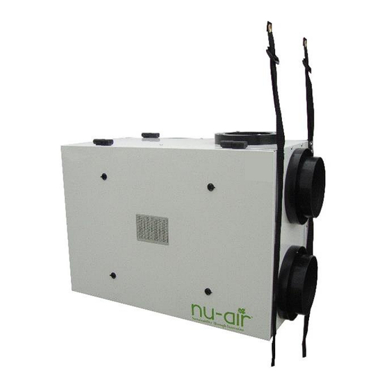
Now Featuring the Nu-Air EZ System.
1. EZ Level suspension straps.
2. EZ Balance pressure ports to measure
and balance air flows.
ES SERIES
OPERATING, MAINTAINING & INSTALLING YOUR HEAT RECOVERY
VENTILATOR
FOR MODELS ES095 ERV, ES115 ERV, ES100, ES150, ES160, ES160E, ES170 AND ES210
MANUFACTURED MAY 2015 ONWARD
* LEAVE THIS DOCUMENT WITH THE HOMEOWNER
Specifications, dimensions and ratings may change without notice
.
as a result of ongoing product development and improvements
Rev. 6.7 January 2023
Advertisement
Table of Contents

Related Manuals for Nu-Air ES115E ERV


Summary of Contents for Nu-Air ES115E ERV
- Page 1 ES SERIES OPERATING, MAINTAINING & INSTALLING YOUR HEAT RECOVERY VENTILATOR FOR MODELS ES095 ERV, ES115 ERV, ES100, ES150, ES160, ES160E, ES170 AND ES210 MANUFACTURED MAY 2015 ONWARD * LEAVE THIS DOCUMENT WITH THE HOMEOWNER Specifications, dimensions and ratings may change without notice as a result of ongoing product development and improvements Rev.
- Page 2 NEVER attempt to repair or service any internal component of this H/ERV while the unit is plugged in or running. DO NOT use your ventilation system to exhaust flammable fumes or gasses. ALWAYS contact your Nu-Air representative if you have any questions or comments about the operation or maintenance of your Nu-Air H/ERV—we are here to help you!
-
Page 3: Table Of Contents
TABLE OF CONTENTS SYSTEM FUCTION/OPERATING TIPS ........................3 INSTALLATION ................................4 Installation Supplies, Standard Issue Items ................... 4 Installer's Responsibilities ........................4 Installation System Options ........................5 Ducting to The Outside ..........................7 Mounting & Noise Control ........................8 Ductwork ..............................9 Drain Connections .......................... -
Page 4: System Fuction/Operating Tips
1. SYSTEM FUCTION/OPERATING TIPS A. Powerful, centrifugal blowers bring fresh air into your home while an equal amount of stale, humid air is exhausted to the outside. This is NU-AIR’s balanced central ventilation system. B. Incoming fresh air is filtered before flowing through the heat exchange core. -
Page 5: Installation
▪ Heat Recovery Core ▪ Drain Hose Assembly ▪ Balancing dampers are NOT REQUIRED. ES Series HRVs from Nu-Air are equipped with a system which allows the installer to adjust each motor in both high and low speed. ▪ Removable terminal blocks for timers, remote controls, furnace interlock. A 4-wire terminal block for 12 VDC ES Series controls and a 10-wire terminal block for 24 V controls are provided with the unit. -
Page 6: Installation System Options
Installation System Options Before installing your HRV, please read these instructions for correct installation. The Nu-Air HRV is a self-contained system that is ready to be installed. - Page 7 2.3.2. The Extended Exhaust System This system uses the HRV in conjunction with a forced air furnace distribution system. In this system the HRV supply air to the house is introduced into the return duct of the forced air furnace. Separate, additional ductwork is used to transfer stale air from the wet rooms to the HRV.
-
Page 8: Ducting To The Outside
the furnace. This allows proper mixing and ensures appropriate air temperature at the furnace heat exchanger in cold weather. For fuel-fired mid and high efficiency furnaces a minimum temperature of 15.5º C (60º F) is recommended at the heat exchanger (check the furnace manufacturer’s specifications). 3) To ensure quiet operation of ENERGY STAR qualified HRV/ERVs, each product should be installed using sound attenuation techniques, such as using a flexible connector between the unit and the rigid- pipe supply and return ducts. -
Page 9: Mounting & Noise Control
For maximum efficiency, the HRV should be installed in a heated area. The HRV is designed to be hung from the ceiling by way of the anti-vibration straps supplied. Avoid hanging the HRV directly below a bedroom or other quiet area. Your unit comes with Nu-Air EZ-Level adjustable hanging straps for easy mounting and leveling. -
Page 10: Ductwork
Ductwork An engineer or other qualified person should design the duct system. • Duct runs should be straight with minimum bends and elbows. • Ensure joints are tight-fitting and sealed with duct tape or sealer. • Use galvanized duct whenever possible. Although flexible duct can be used, its use should be restricted to areas indicated (to outside hoods and in unheated spaces). -
Page 11: Drain Connections
mechanical rooms that might contain combustion equipment. The Novoclimat standard of Quebec, Canada, requires this method of ducting for 5 port ventilators. Drain Connections Access to a drain or sump is required for HRV condensate. Care should be taken to run the condensate tube where it cannot freeze. -
Page 12: Furnace Interlock
Furnace Interlock For simplified (return/return) duct systems, it is mandatory that the HRV be interlocked with the furnace blower such that the furnace fan runs when the HRV is on to distribute supply air throughout the space. For extended exhaust systems, furnace interlock is recommended. Refer to local building codes. THERMOSTAT TERMINALS THERMOSTAT TERMINALS COOLING SYSTEM... -
Page 13: Balancing Air Flows
Balancing Air Flows Balanced air flow between the supply and exhaust air streams is essential to the performance of an HRV or ERV. With the ES Series, changing motor speeds or balancing is quick and simple with two buttons recessed slightly into the unit’s cabinet—see next section. NO BALANCING DAMPERS ARE REQUIRED. - Page 14 1. Before placing the manometer, reset it to zero. If using a magnehelic gage, ensure the gage is placed plumb and level. 2. According to the air flow to be measured, connect tubing from instrument to EXHAUST air flow or FRESH air flow pressure taps (see illustrations at right).
-
Page 15: Control Options & Control Wiring
3. CONTROL OPTIONS & CONTROL WIRING Your machine is equipped for remote controls. Options include humidity sensing, off-on control, intermittent and continuous modes, recirculation as well as high speed control from dehumidistat or timer(s). Your unit can accommodate both ES Series and Windsor Series or other 24 VAC controls. Both types of control may be used in the same installation, with ONE type of central control (12 VDC or 24 VAC).Various means of controlling the system are described below. - Page 16 3.1.2. ES Lumina (p/n NAV-561) The Lumina offers a complete package of control options in one unit. This product replaces the ES-DVC March 2015. Features: • Backlit LCD Screen • Generously sized navigation keys • Intuitive user interface • Interchangeable face plate to mount chosen face plate colour •...
-
Page 17: Nav-460 20-40-60 Minute Timer
OR a unit-mounted jumper wire) set to one of its operation modes Windsor Series Controls & Other 24 V Control Options Nu-Air offers 24 VAC controls which provide basic functions and easy operation. Other 24 VAC controls might also be used. - Page 18 Using a 3 mm flat head screwdriver, connect 2-4-conductor wire according per requirements to the 24 VAC (10-wire) removable terminal block provided. 3.3.1.1. DSTAT-1 For intermittent high speed operation, connect Nu-Air PN DSTAT-1 to R and Hi terminals. Jumper Option 1: For continuous low speed, connect jumper wire to R and LO terminals.
- Page 19 3.3.1.3. Win-20 Up to 6 Win-20 timers may run off of one system. PWR (red) WIN-20 can be combined with ES Series controls or 24V controls discussed in this document. LED (yellow) For Win-20-2 wiring, R and TS terminals are used. SWITCH (black) If you are using ONLY a WIN-20(s) to control your...
-
Page 20: Status Leds & Mode Of Operation
Status LEDs & Mode of Operation From mid-April, 2013, all control boards are equipped with status lights to indicate mode of operation. CONDITION LED AND STATUS NO LED UNIT/TRANSFORMER IS NOT POWERED UNIT OFF Red is off, Green is blinking slow, every 1 s. Also indicates processor is programmed and running. -
Page 21: Start-Up
4. START-UP • Ensure the controls are connected in accordance with Section 3. • For electrical hook-up, plug into a 120 volt receptacle. • Ensure that the machine is piped to an adequate drainage source, i.e. through the drain hose supplied. -
Page 22: Trouble Shooting
c) Verification that intake and exhaust air flows are properly balanced. d) Re-balancing as necessary. 7. TROUBLE SHOOTING SYMPTOM EXPLANATION ANSWER • • The humidity level seems HRV air flows incorrectly balanced. Balance air flow(s). • • too low. Dehumidistat control set too low. Increase dehumidistat. -
Page 23: Electrical Schematics
8. ELECTRICAL SCHEMATICS ES170/ES160 (HRV and ERV models) p/n 50321 NA-HRV rev F ES100/ES150 ES100/ES150 p/n 50321 NA-HRV rev F Rev 6.7 January 2023... - Page 24 ES210 p/n 50321 NA-HRV rev F p/n 50321 NA-HRV rev F ES095 p/n 50321 NA-HRV rev F Rev 6.7 January 2023...
-
Page 25: Warranties
Delivery, installation, and labour cost are not covered by this warranty. 15 Year HRV Core Warranty If the recovery plastic core in your NU-AIR Heat Recovery Ventilator fails due to a defect in material or workmanship NU-AIR Ventilation Systems Inc. will supply a new core FOB Factory to replace the defective part. -
Page 26: Notes/Service Record
10. NOTES/SERVICE RECORD Rev 6.7 January 2023...
Need help?
Do you have a question about the ES115E ERV and is the answer not in the manual?
Questions and answers