Table of Contents
Advertisement
SERVICE MANUAL
Ver. 2.1 2013.01
*BDP-S185 (S/N)
UK/AUS
1,200,001 ~ 1,499,999
RUS
5,300,001 ~ 5 ,499,999
CH
4,200,001 ~ 4,399,999
System
Laser: Semiconductor laser
Inputs and outputs
(Jack name:
Jack type/Output level/Load impedance)
LINE OUT R-AUDIO-L:
Phone jack/2 Vrms/10 kilohms
DIGITAL OUT (COAXIAL):
Phono jack/0.5 Vp-p/75 ohms
HDMI OUT:
HDMI 19-pin standard connector
LINE OUT VIDEO:
Phono jack/1.0 Vp-p/75 ohms
LAN (100):
100BASE-TX Terminal
USB:
USB jack Type A maximum current 500mA
(For connecting USB device)
ENERGY STAR and the ENERGY STAR mark
are registered U.S. marks. ENERGY STAR is a
registered mark owned by the U.S. government.
(BDP-S185:US/BX18:US)
9-890-789-12
BDP-BX18/S185/S186
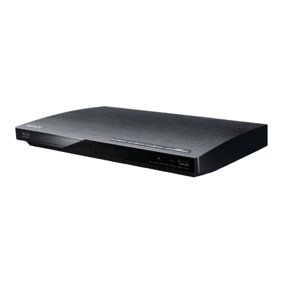
Photo: BDP-S185
Remote : RMT-B119A
IMPORTANT INFORMATION
Use only for serial number (S/N) listed
Note :
**BDP-S185 (S/N)
AEP (Black)
4000001 ~ 4499999
3300001 ~ 3499999
**BDP-S186 (S/N)
AEP (Silver)
4500001 ~ 4999999
3600001 ~ 3999999
SPECIFICATIONS
General
Power requirements:
Power consumption:
Dimensions (approx.):
Mass (approx.):
Operating temperature:
Operating humidity:
Supplied accessories
Sony Corporation
Home Entertainment Business Group
RMT-B120P/B119A/B109C
*Australian/NZ Model
***Canadian Model
***BDP-S185 (S/N)
US
7400001 ~ 8499999
5200001 ~ 5999999
2000001 ~ 4999999
CND
8700001 ~ 9999999
***BDP-BX18 (S/N)
US
2000001 ~ 4999999
CND
8700001 ~ 9999999
120V AC, 60Hz (BDP-S185:US, CND/BX18)
220 – 240V AC, 50/60Hz (AEP,UK, AUS, RUS, CH)
10 W
290mm × 196mm × 43mm
(11
in. × 7
in. × 1
in.)
1/2
3/4
3/4
(width/depth/height) incl. projecting parts
1.1kg (2 lb 6
oz)
3 / 4
5 ºC to 35 ºC(41 F to 95 F)
º
º
25 % to 80 %
• Audio/video cable (phono plug ×3) (1)(AUS,RUS,US,CND)
• HDMI cable (1) (BDP-S185:CN/BX18)
• Remote commander (remote) (1)
• Size AA (R6) batteries (2)
Specifications and design are subject to change
without notice.
TM
BLU-RAY DISC / DVD PLAYER
Published by Document Design Dept.
*Chinese Model
*UK Model
*Russian Model
BDP-S185
**AEP Model
BDP-S185/S186
***US Model
BDP-S185/BX18
Tiss : Refer HV12BDK535
2013A6900-1
© 2013.01
Advertisement
Table of Contents

Related Manuals for Sony BDP-S186


Summarization of Contents
Service Manual Overview
Important Information
Critical notes and serial number guidance for service personnel.
Product Specifications
Technical details including power, dimensions, operating conditions, and connectivity.
Safety Procedures and Warnings
Safety Check-out Steps
Mandatory safety checks to perform after completing repairs.
Leakage Current Test
Procedure for testing AC leakage current from exposed metal parts.
Laser Safety Precautions
Important warnings regarding laser emission and safe observation distances.
Safety-Related Component Warning
Identification and handling instructions for safety-critical components.
Unleaded Solder Handling
Information on the characteristics and handling of unleaded solder.
Section 1: Service Notes
Disc Removal Procedure
How to manually eject a disc when the tray cannot be opened.
Optical Device Replacement
Steps for replacing the optical device, including software and data decoding.
Test Disc Operations
Guidance on using test discs to verify player operation and output.
Drive Repair and BU Handling
Comprehensive procedures for drive repair, BU replacement, data handling, and loading.
Assembly Cautions
Precautions to take when disassembling or assembling internal components.
Section 2: Disassembly Procedures
Disassembly Flowchart
Overview of the disassembly sequence.
Tray Cover Assembly Removal
Procedure to remove the tray cover.
Top Panel Removal
Step-by-step guide for removing the top panel.
FR-316 Board Removal
How to remove the FR-316 board.
Switching Regulator Removal
Procedure for removing the switching regulator.
MB-144 Board Removal
Steps to remove the MB-144 board.
Drive Unit Removal
How to remove the drive unit.
Circuit Board Locations
Diagram showing the placement of main circuit boards.
Section 3: Block Diagrams
Overall Block Diagram
High-level functional overview of the player's internal architecture.
DSP Block Diagram
Detailed diagram of the Digital Signal Processor and its related components.
AV Out Block Diagram
Schematic illustrating the audio and video output circuitry.
USB, Ethernet, and Wi-Fi Block Diagram
Functional diagram for the player's connectivity interfaces.
Power Block Diagram
Schematic showing the power distribution and regulation circuitry.
Section 4: Schematic Diagrams
Schematic Diagram Notes
Common notes, symbols, and conventions used in schematic diagrams.
Frame and FR-316 Board Schematics
Circuit diagrams for the player's frame and the FR-316 board.
MB-144 Board Schematics
Detailed circuit diagrams for the MB-144 board covering multiple functions.
MB-144 Board Waveforms
Illustrations of key signal waveforms for troubleshooting the MB-144 board.
Section 5: Printed Wiring Boards
Printed Wiring Board Notes
Common notes, symbols, and conventions for printed wiring board diagrams.
FR-316 Board PWB Layout
Layout diagrams for the FR-316 board, showing component placement.
MB-144 Board PWB Layout
Layout diagrams for the MB-144 board, illustrating component placement.
Section 6: IC Pin Function Descriptions
MB-144 IC101 Pin Functions
Detailed pinout and function description for the MB-144 main system control IC.
MB-144 Various Interface Pin Functions
Pin functions for audio, video, USB, Ethernet, and other interfaces on the MB-144 board.
MB-144 Control and Memory Interface Pins
Pin functions for DRAM, NAND Flash, and various control interfaces.
MB-144 Motor and Laser Control Pins
Pin functions related to feed motors, laser control, and tray interface.
Section 7: Service Mode Operations
Entering Service Mode
Methods to access the player's service mode via front panel or remote controller.
Service Mode Menu Functions
Overview of available diagnostic and maintenance functions within service mode.
Function Support List
Compatibility matrix of service functions across different player models.
Service Mode Menu Navigation
Guidance on navigating service menus and interpreting front panel display.
Section 8: Error Log List
Error Log Information
Table detailing error codes, their categories, and potential causes.
Section 9: Troubleshooting Flowcharts
Main Troubleshooting Flowchart
Primary diagnostic flow for identifying and resolving player issues.
Power Supply Troubleshooting
Flowchart to diagnose and resolve power supply related problems.
Audio Section Troubleshooting
Diagnostic steps for issues related to audio output and processing.
Video Section Troubleshooting
Flowchart for troubleshooting problems with video output and display.
FR-316 Board Troubleshooting
Diagnostic steps specific to the FR-316 board and its associated controls.
Drive Troubleshooting
Flowchart for diagnosing and resolving issues with the disc drive mechanism.
Remote Control Troubleshooting
Steps to diagnose problems with the remote control's functionality.
White LED Troubleshooting
Specific diagnostic steps for issues related to the white LED indicator.
Network Troubleshooting
Flowcharts for diagnosing Ethernet and USB device connection problems.
Section 10: Repair Parts List
Exploded Views of Major Assemblies
Visual breakdown of parts for case, main chassis, and BD drive assemblies.
Accessories List
List of standard accessories included with the player.
Electrical Parts List
Detailed list of all electrical components, including part numbers and descriptions.
Need help?
Do you have a question about the BDP-S186 and is the answer not in the manual?
Questions and answers