Table of Contents
Advertisement
Quick Links
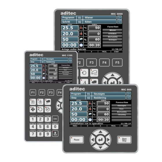
MIC 900 / MIC 1100 / MIC 3000
Measurement and
Control technology
Hardware development
Software development
Specialised electronics
Food technology
Process visualisation
User Manual
Process controller
V00.21
Issue 17.08.2021_00
aditec gmbh
Talweg 17
D-74254 Offenau
Tel.:+49(0)7136 96122-0
Fax:+49(0)7136 96122-20
www.aditec.net
eMail: info@aditec.net
Advertisement
Table of Contents

Related Manuals for aditec MIC 1100


Summarization of Contents
1 Introduction
1.1 Overview
Describes the controller's purpose, capabilities, and interfaces for industrial use.
1.2 Display and Operating Area
Focuses on the physical interface layout, including touch panel and control buttons.
1.2.1 Input and Display Touch Panel
Details the touch screen functionality and its role in changing settings.
1.2.2 Control Buttons
Explains the physical buttons, their functions, and LED indicators for operation.
1.3 On-Screen Keypad Functions
Details the virtual keyboard layout and the functions of its keys.
1.3.1 MIC 1100/3000 Operating Buttons
Specifics for number and letter button input on MIC 1100/3000 models.
1.4 Entering Numerical Values
Core operation for inputting data using the numerical pad.
1.4.1 MIC3000 Control Buttons (Number Buttons)
Specifics for MIC3000 number button input.
1.4.2 Screen Lock
Security feature to prevent accidental input by locking the interface.
2 Standby Mode
2.1 Program Groups and Images
How programs are organized and displayed in the standby interface.
2.2 Selecting a Program
Core task for starting operations by choosing a program.
2.2.1 Program Number
Method for program selection via entering its unique number.
2.2.2 Program Name
Method for program selection via entering its name.
2.2.3 Favourites List
User-defined shortcuts for quick access to frequently used programs.
2.3 Selecting a Step
Navigating within a program to select specific steps.
2.3.1 Process Name Selection
Method for step selection by matching the process name.
2.3.2 Step Number Selection
Method for step selection by entering its sequential number.
2.3.3 Task Bar Step Navigation
Using the task bar for changing between program steps.
2.4 Actual and Nominal Values
Critical for monitoring current parameters and target setpoints.
2.5 Program Run Times
Information on current step and remaining program duration.
2.6 Optional Displays
Customizing information shown on screen during operation.
2.6.1 Optional Nominal Values
Displaying additional setpoints like Delta or FC value.
2.6.2 Process Display
Shows sequence of program steps and their current status.
2.6.3 Aggregate and Relay Display
Status of system components and relays.
2.6.4 System Status Messages
Informational messages about system status.
2.6.5 Alarm Messages
Critical alerts indicating malfunctions or issues.
2.6.6 Control Loops and Measured Values
Advanced monitoring of process variables and control loops.
2.6.7 Favourites
User-defined program list for quick access.
2.6.8 Aggregate Buttons
Manual control inputs for specific functions.
2.6.9 Aggregate Modules
Status of system components controlled by modules.
2.6.10 Switching to Next Step
Program flow control actions for advancing steps.
2.6.11 Analogue Outputs
Technical output information for specific analogue signals.
2.7 Task Bar Navigation
Key interface element for general navigation and access.
2.7.1 Start Page/Profiles
Accessing the main standby screen or user profiles.
2.7.2 Programs
Accessing the program selection interface.
2.7.3 Editing a Program Step
Modifying individual steps within a program.
2.8 Information Bar
Status and message display area at the bottom of the screen.
4 Programming Mode
4.1 Selecting a Program
Initial step in programming for selecting or editing programs.
4.2 Setting Up a Favourites List
Customizing program access for frequent use.
4.3 Editing Program Steps
Modifying individual steps within a program.
4.3.1 Display for Editing Program Steps
Interface for viewing and modifying program steps.
4.3.2 Assign Program Images
Visual customization for programs by assigning images.
4.3.3 Entering Nominal Values
Setting process parameters for each step.
4.3.4 Entering a Delta Value
Specific parameter input for temperature control.
4.3.5 Setting Up Repetitive Steps
Creating loops or sequences within program steps.
4.3.6 Copying, Deleting, and Adding Programs/Steps
Program and step management operations.
4.4 Linking Programs
Connecting programs sequentially for complex processes.
4.5 Create/Change Cleaning Times
Setting cleaning sequences and durations for processes.
4.6 Setting Up a Program with VisuNet
Integration and setup using external VisuNet software.
4.6.1 Enabling VisuNet
Activating the controller for VisuNet service.
4.6.2 Editing Programs with VisuNet
Using VisuNet software for program editing.
5 Program Start
5.1 Instant Start
Immediate program execution upon command.
5.1.2 Start with Time of Day
Scheduled program execution at a future date and time.
5.1.3 Starting with Batch Number
Tracking production batches with unique identifiers.
5.1.4 Sensor Log On/Off
Sensor activation status for data logging purposes.
5.1.5 Operating Hours Messages
Status related to device usage time tracking.
6 Operating Mode
6.1 Shut-Down Conditions
Criteria that terminate a program step.
6.1.1 Negative Core Shut-Down
Specific cooling/showering condition for termination.
6.1.2 FC Value
Germ reduction metric used as a shut-down condition.
6.2 Transient Changes to Nominal Values
Temporary adjustments to setpoints during operation.
6.3 Batch Number During Operation
Checking or changing batch information while a program is running.
6.4 Switching to Next/Previous Step
Program flow control during manual operation.
6.5 Pausing a Program
Temporarily stopping program execution.
6.6 Single Step Control
Controlling program progression on a step-by-step basis.
6.7 Alarm Signal
Handling and acknowledging system alerts.
6.8 Maximum Step Time Display
Information on step duration limits.
6.9 Checking Cleaning Times
Monitoring cleaning process status.
6.10 Fast Dehumidifying
Activation and status of the dehumidifying function.
8 Profiles
8.1 Date and Time
Setting the system clock and date.
8.2 Enabling Data Logger
Recording operational data for analysis.
8.3 Enabling and Disabling a Signal
Controlling signal aggregates based on time.
8.4 Enabling Batch Number
Setting up batch number entry for programs.
8.5 Loading Programs
Importing program data from external sources.
8.5.1 Loading Programs
Specifics of loading programs from a USB stick.
8.5.2 Copying Programs onto USB
Saving programs to a USB drive.
8.5.3 Saving Data Logger Data onto USB
Transferring logged data to a USB drive.
8.6 Show Versions
Displaying system version and hardware information.
8.7 Administrators (from V00.07)
User management, access rights, and PIN configuration.
8.7.1 Configuration/Changes to Administrator Settings
Modifying user access rights and global settings.
8.7.1.1 Changing User Names, Access Rights, Global Administrator Settings
Detailed administrator configuration interface.
8.7.1.2 Changing the User PIN
Managing user authentication PINs.
8.7.2 Display of Current User
Identifying the currently logged-on user.
11 Connection Diagram
11.1 MIC 900
Specific wiring diagram for the MIC 900 model.
11.2 MIC 1100
Specific wiring diagram for the MIC 1100 model.
11.3 MIC 3000
Specific wiring diagram for the MIC 3000 model.
12 Technical Data
12.1 MIC 900
Technical specifications for the MIC 900.
12.2 MIC 1100
Technical specifications for the MIC 1100.
12.3 MIC 3000
Technical specifications for the MIC 3000.
Need help?
Do you have a question about the MIC 1100 and is the answer not in the manual?
Questions and answers