Table of Contents
Advertisement
Quick Links
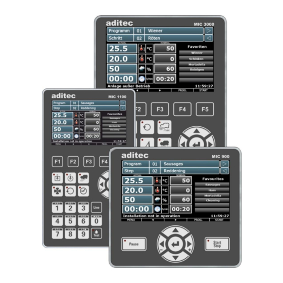
MIC 900 / MIC 1100 / MIC 3000
Measurement and
Control technology
Hardware development
Software development
Specialised electronics
Food technology
Process visualisation
User Manual
Process controller
V00.21
Issue 17.08.2021_00
aditec gmbh
Talweg 17
D-74254 Offenau
Tel.:+49(0)7136 96122-0
Fax:+49(0)7136 96122-20
www.aditec.net
eMail: info@aditec.net
Advertisement
Table of Contents


Need help?
Do you have a question about the MIC 900 and is the answer not in the manual?
Questions and answers
Why all the temperatures are emptied in the program?
All the temperatures in the Aditec MIC 900 program may be cleared when a sensor defect occurs, such as a broken or short-circuited core or humidity sensor. In such cases, the display shows “EEE” for a sensor break or “---” for a short circuit. After replacing the sensor, the temperatures must be checked and the controller may need re-calibration by a service technician.
This answer is automatically generated