Table of Contents
Advertisement
Small programmable controller
for cooking, baking and kettle units
Measurement and
Control technology
Hardware development
Software development
Specialised electronics
Food technology
Process visualisation
MKA 120
User Manual
Version V20.16
Issue 26.10.2022_00
aditec gmbh
Talweg 17
D-74254 Offenau
Tel.:+49(0)7136 96122-0
Fax:+49(0)7136 96122-20
www.aditec.net
eMail: info@aditec.net
Advertisement
Table of Contents

Related Manuals for aditec MKA 120


Summary of Contents for aditec MKA 120
- Page 1 Small programmable controller MKA 120 for cooking, baking and kettle units User Manual Version V20.16 Issue 26.10.2022_00 Measurement and aditec gmbh Control technology Talweg 17 Hardware development D-74254 Offenau Software development Tel.:+49(0)7136 96122-0 Specialised electronics Fax:+49(0)7136 96122-20 Food technology www.aditec.net Process visualisation eMail: info@aditec.net...
-
Page 2: Table Of Contents
User Manual MKA 120 Conforms to 1 Contents 1 Contents ............................... 2 2 Introduction ............................5 2.1 Overview ............................5 2.2 Controller characteristics ........................ 5 3 Operating controls ..........................6 3.1 Button functions ..........................7 3.1.1 Shortcut buttons ........................7 3.2 LED Display ............................ - Page 3 User Manual MKA 120 Conforms to 8.1.3 Optional control loops ......................25 8.2 Switching into a different step .......................25 8.3 Status bar ............................26 8.3.1 Messages (system status messages) ..................26 8.3.2 Alarms ............................26 8.4 Alarm signal ..........................27 8.4.1 Enabling signal relays ......................27 8.5 Program runtime, operating time display in operating mode ............28...
- Page 4 User manual MKA 120 Conforms to Symbols used in this user manual The following symbols are used in this user manual to highlight important information: Symbol Description See page / press button Press several buttons simultaneously This symbol indicates a useful hint or gives a tip ...
-
Page 5: Introduction
An optional serial interface allows for data transfers between the controller MKA120 and a PC. The controller can be programmed via a PC with the installed aditec service program. The connection is made via a mini USB or optionally via LAN or a serial interface RS485, respectively. -
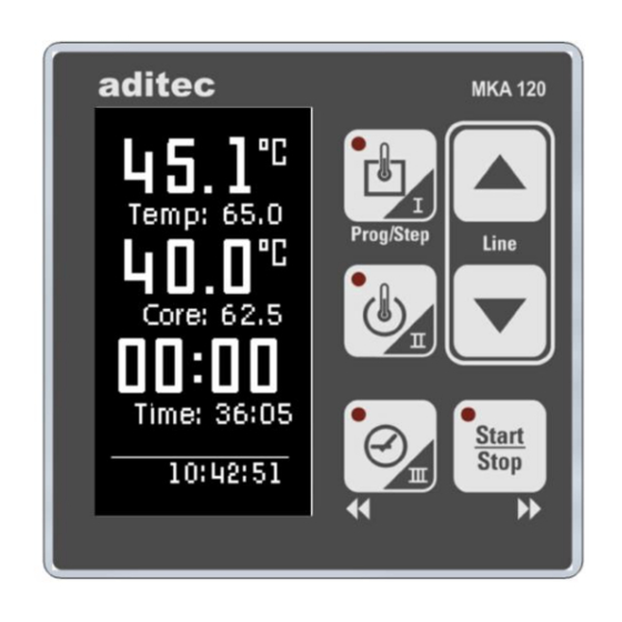
Page 6: Operating Controls
User manual MKA 120 Conforms to 3 Operating controls Figure 1: Operating controls Actual value temperature (Temp) / short cut button 1 Nominal values / short cut button 1 Actual value core temperature / short cut button 2 Nominal values short cut button 2... -
Page 7: Button Functions
User manual MKA 120 Conforms to 3.1 Button functions Button Description Function Temperature Shortcut button for entering the following „Temp“ nominal values: temperature (min, max), Delta Core temperature Shortcut button for entering the following „Core“ nominal values: core temperatur (min, max) -
Page 8: Led Display
User manual MKA 120 Conforms to 3.2 LED Display LED off LED on Relevance LED „is flashing“ when a nominal value is Temperature changed ( see how to configure a program). (Temp) LED „is flashing“ when a nominal value is changed (see how to configure a program). -
Page 9: General Text Entry (Edit Box)
User manual MKA 120 Conforms to 4.2 General text entry (Edit box) How to enter text: ▪ Cursor is flashing in the first position: „_“. ▪ When you are making an entry the cursor is at first in the position „_“. Use the... -
Page 10: Check Boxes
User manual MKA 120 Conforms to 4.4 Check boxes Check boxes allow you to set e.g. a state. When a check box is focussed (frame around the info text) you can change its state to selected (Relay 1) or not selected (Relay 2,3) by using the ‚Line‘... -
Page 11: Leaving A Code
User manual MKA 120 Conforms to 4.7 Leaving a code There are two ways of leaving a code setting. Option 1: Leaving the code to go back to the previous window. Example: leaving Code 2001 Buttons Displays Comment Press the ‚Line‘... -
Page 12: Entering Nominal Values
User manual MKA 120 Conforms to 5.1 Entering nominal values The entry function for nominal values will automatically be terminated after 10 seconds if no further key pad buttons are pressed. The nominal value that was entered last is saved. -
Page 13: Optional Nominal Values
User manual MKA 120 Conforms to Be aware No pre-set step time: If you have not entered a step time, time will be counted forward while the step is running. (in this way you always know how long the step has been in operation). -
Page 14: Aggregate Modules (Direct Relay Actuation)
User manual MKA 120 Conforms to In order to avoid confusion, two further specifications can be added to the F-value, e.g. FC 121-10 (z-value), this means that at a core temperature of 121,1°C and a time of one minute, the F-value = 1. If the temperature is increased by 10°C, the F-value increases 10-fold. - Page 15 User manual MKA 120 Conforms to Depending on the switching behaviour that was pre-programmed by the service technician, different nominal values are available to the operator. During operation the current actual value and the current nominal value are shown. If there is a pre-set switch-on and switch-off interval for an aggregate module, they will be shown alternately in the actual value display.
-
Page 16: Optionale Control Loops
User manual MKA 120 Conforms to 5.6.4 Optionale control loops Up to 3 optional regulator can be programmed. The configuration determines which nominal values may be entered and they can vary depending on the system. In this way the end user has the option of programming the nominal values of these regulators in the different program steps. -
Page 17: Working With Single Step Control
User manual MKA 120 Conforms to 2) The programis paused and th edisply will show the message „Temperature reached!“, the „Start/Stop“ button will be flashing. The program will only be resumed when the „Start/Stop“ button is pressed and the step time counter will then start. -
Page 18: Standby
User manual MKA 120 Conforms to 6 Standby As soon as the controller is connected to a power source it will automatically boot up. This can take up to 1 minute. Be aware Please do not use pointy objects to operate the controller (e.g. pointed fingernails, ball points sharpened pencils or screw drivers). -
Page 19: Program Setup
User manual MKA 120 Conforms to Hint Press any buttton, to leave standby. By pressing and holding the „Start“ button you can always return to standby. (When the system is not in operation). 7 Program setup Be aware The number of programs available may vary depending on the type of system you have got and the application. -
Page 20: Program Start
User manual MKA 120 Conforms to Saving nominal value LED off Nominal value is flashing Changing optional nominal values LED flashing LED flashing 7.2 Program start 7.2.1 Starting from standby LED is lit up / Temperature is regulated wird geregelt... -
Page 21: Starting A Program With Starting Time
User manual MKA 120 Conforms to 7.2.4 Starting a program with starting time Changing the Starting a LED is lit up / start time Please enter program Temperature Start time is regulated Next input field Relay states 3 Sec. He(Heating on) 3 Sec. -
Page 22: Changing Nominal Values Within A Step
User manual MKA 120 Conforms to 7.3.2 Changing nominal values within a step Selecting a nom. value to be activating/deactivating a process changed Changing a nom. value Hint Only nominal values that have been enabled in the configuration can be entered/ changed here. - Page 23 User manual MKA 120 Conforms to Copying a program: The program to be copied is shown in box Select the program number you want to copy Confirm your entry by pressing Enter (box ) or cancel by pressing Cancel (box Deleting a program Deleting a previously selected program.
-
Page 24: Program End
User manual MKA 120 Conforms to Inserting a step Inserting the previously selected step. Confirm your entry by pressing Enter (box ) or cancel by pressing Cancel (box Be aware When you press the „Enter“ button the step will be automatically copied. -
Page 25: Aggregate And Relay Display
User manual MKA 120 Conforms to If additional nominal values or aggregate buttons (e.g. FC-value, Delta temperature, optional regulators) have been enabled, the relevant nominal and actual values are displayed in operating mode and can be changed transiently. Be aware If you change a nominal value while a step is running, then this value applies only for the duration of the current step. -
Page 26: Status Bar
User manual MKA 120 Conforms to If the program and step number are displayed during operation, you can use the “Line” button to select the step number. Once you have selected a step number (Stp: 1 is flashing), you can use the arrow buttons „up“... -
Page 27: Alarm Signal
User manual MKA 120 Conforms to 8.4 Alarm signal If an alarm has occurred, for example through a sensor break or a digital input (alarm), the box „Step“ will be flashing alternately (light and dark).On the status bar the alarm and its cause (e.g. -
Page 28: Program Runtime, Operating Time Display In Operating Mode
User manual MKA 120 Conforms to Settings during operation: If an alarm has occurred (signal relay has been energised), it can be acknowledged by pressing the button for 3 sec. 3 sec. If no alarm has occurred, the signal relay can be activated or de-activated during operation by pressing the button for 3 sec. -
Page 29: Profile Settings
User manual MKA 120 Conforms to 9 Profile settings Under profiles all settings are complied for the operator. You do not need a passwort to access profiles. The settings under this code have no effect on the controller settings. Menu item... -
Page 30: Status Bar Display (Status Bar)
User manual MKA 120 Conforms to Automatic change-over summer/winter time The automatic change-over summer/winter time is active when the check box „Daylight Time“ has been activated. This means the clock is moved forward one hour at 2:00a.m. on the last Sunday in March and moved back one hour at 3a.m. -
Page 31: Enabling A Batch Number
This enables you to monitor and log temperature profiles and processes ensuring comprehensive quality control of the treated products in compliance with HACCP and IFS (ISO 9000). Please contact aditec or your service technician in order to enable this function. -
Page 32: Version Number Display
User manual MKA 120 Conforms to 9.5 Version number display Profiles Version 3 Sec. This code setting allows you to see the software version of the controller. You need the version number in case you have to contact the manufacturer. -
Page 33: Screen Saver
User manual MKA 120 Conforms to 9.7 Screen saver (from Version 20.05 onwards) Profile Screen saver 3 Sec. Screen saver settings Factory setting: Screen saver:ON Waiting time: 5 min Code number Activating/ de-activating – Waiting time (00:10 99:59) Test... -
Page 34: List Of Errors (Possible Problems)
User manual MKA 120 Conforms to 11 List of errors (possible problems) Occurring problem Possible cause Possible action Program does not start Program is empty Pre-program a process „Start/Stop“button. Pre-set start time has been Press the entered („Start“ button is flashing) Please check the three –core... -
Page 35: Connecting The Controller To A Pc
VisuNet. • The visualisation program aditec VisuNet allows you to connect the controllers to a superordinate surveillance system. This enables you to monitor and log temperature and humidity profiles of processes ensuring comprehensive quality control of the treated products... -
Page 36: Connection Via A Rs485 Interface
If you have entered the PIN number incorrectly 3 times in a row, you can still enable VisuNet with a PUK number. If both numbers have been entered incorrectly 3 times in a row, the controller will have to be sent back to aditec. Hint You will receive a separate user manual for VisuNet with instructions on how to install and operate it. - Page 37 User manual MKA 120 Conforms to Select Base or Comfort Enter PIN or PUK Display of remaining attempts to enter PIN VisuNet Base enabled, Comfort disabled Select Base or Comfort Information Confirm PIN or PUK Enter PIN or PUK VisuNet Comfort enabled If VisuNet Comfort has already been enabled the diplay will show the message „VisuNet Comfort enabled!“...
-
Page 38: Connection Diagram
User manual MKA 120 Conforms to 13 Technical data See separate data sheet 14 Connection diagram 14.1 Expansion cards / Options Issue 07.07.2021_01 Page 38... -
Page 39: Index
User manual MKA 120 Conforms to 15 Index Linking ........... 21, 33 List box ..........10, 11, 38 actual values ........15, 24, 31 Aggregate and relay display ...... 24 Aggregate modules ....... 14, 24 Maintenance ..........5, 34 aggregates ........... 14 Messages ............. - Page 40 User manual MKA 120 Conforms to Version number ........... 30 VisuNet ...... 5, 15, 25, 30, 34, 35, 36 Waiting mode .......... 8, 20 Hint For further search terms not included in the index directory, please use the search function in Adobe Acrobat Reader.
-
Page 41: Safety Instructions
User manual MKA 120 Conforms to 16 Safety instructions To avoid any danger of electrocution, the housing must never be removed nor opened at the back. None of the parts inside can be serviced by the user himself. Leave the servicing to the experts! To avoid fire or electrocution this appliance must not be exposed to humidity or rain. - Page 42 Conforms to Hint Never make any technical alterations to the appliances, unless they were specifically approved by aditec GmbH. Unauthorized alterations will invalidate your warranty. For enquiries, orders and repair enquiries, please contact us at the following address: Issue 07.07.2021_01...
Need help?
Do you have a question about the MKA 120 and is the answer not in the manual?
Questions and answers