Table of Contents
Advertisement
CDX-GT52UM/GT470UE/GT470UM/GT472UE/
SERVICE MANUAL
Ver. 1.0 2012.07
• The tuner and CD sections have no adjustments.
(US and Canadian models only)
FOR UNITED STATES CUSTOMERS. NOT
APPLICABLE IN CANADA, INCLUDING
IN THE PROVINCE OF QUEBEC.
POUR LES CONSOMMATEURS AUX
ÉTATS-UNIS. NON APPLICABLE AU
CANADA, Y COMPRIS LA PROVINCE DE
QUÉBEC.
(US and Canadian models only)
AUDIO POWER SPECIFICATIONS
CEA2006 Standard
Power Output: 17 Watts RMS 4 at
4 Ohms < 1% THD+N
SN Ratio: 80 dBA
(reference: 1 Watt into 4 Ohms)
Tuner section
(US and Canadian models)
FM
Tuning range: 87.5 – 107.9 MHz
Antenna (aerial) terminal:
External antenna (aerial) connector
Intermediate frequency: 25 kHz
Usable sensitivity: 8 dBf
Selectivity: 75 dB at 400 kHz
Signal-to-noise ratio: 80 dB (stereo)
Separation: 50 dB at 1 kHz
Frequency response: 20 – 15,000 Hz
AM
Tuning range: 530 – 1,710 kHz
Antenna (aerial) terminal:
External antenna (aerial) connector
Intermediate frequency:
9,115 kHz or 9,125 kHz/5 kHz
Sensitivity: 26 μV
Tuner section
(AEP and UK models)
FM
Tuning range: 87.5 – 108.0 MHz
Antenna (aerial) terminal:
External antenna (aerial) connector
Intermediate frequency: 25 kHz
Usable sensitivity: 8 dBf
Selectivity: 75 dB at 400 kHz
Signal-to-noise ratio: 80 dB (stereo)
Separation: 50 dB at 1 kHz
Frequency response: 20 – 15,000 Hz
MW/LW
Tuning range:
MW: 531 – 1,602 kHz
LW: 153 – 279 kHz
Antenna (aerial) terminal:
External antenna (aerial) connector
Intermediate frequency:
9,124.5 kHz or 9,115.5 kHz/4.5 kHz
Sensitivity: MW: 26 μV, LW: 45 μV
9-893-531-01
Sony Corporation
2012G33-1
©
2012.07
Published by Sony Techno Create Corporation
GT472UM/GT474UM/GT520U/GT525U
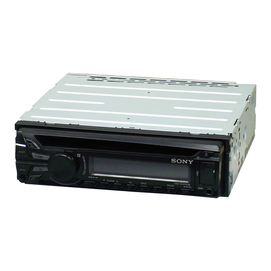
Photo: CDX-GT470UM
Model Name Using Similar Mechanism
Mechanism Type
Optical Pick-up Name
SPECIFICATIONS
Tuner section
(Russian model)
FM
Tuning range:
CDX-GT472UE/CDX-GT470UE
FM1/FM2: 87.5 – 108.0 MHz (at 50 kHz step)
FM3: 65 – 74 MHz (at 30 kHz step)
CDX-GT470UM
Tuning range: 87.5 – 108.0 MHz
Antenna (aerial) terminal:
External antenna (aerial) connector
Intermediate frequency: 25 kHz
Usable sensitivity: 8 dBf
Selectivity: 75 dB at 400 kHz
Signal-to-noise ratio: 80 dB (stereo)
Separation: 50 dB at 1 kHz
Frequency response: 20 – 15,000 Hz
MW/LW
Tuning range:
MW: 531 – 1,602 kHz
LW: 153 – 279 kHz
Antenna (aerial) terminal:
External antenna (aerial) connector
Intermediate frequency:
9,124.5 kHz or 9,115.5 kHz/4.5 kHz
Sensitivity: MW: 26 μV, LW: 45 μV
Tuner section
(E, Mexican, Argentina, Korean
and Indian models)
FM
Tuning range:
For non-Argentine models:
87.5 – 108.0 MHz (at 50 kHz step)
87.5 – 108.0 MHz (at 100 kHz step)
87.5 – 107.9 MHz (at 200 kHz step)
For Argentine models:
87.5 – 107.9 MHz
FM tuning step (for non-Argentine models):
US, Canadian, E, Mexican, Argentina, Korean and Indian models
50 kHz/100 kHz/200 kHz switchable
Antenna (aerial) terminal:
External antenna (aerial) connector
Intermediate frequency: 25 kHz
Usable sensitivity: 8 dBf
Selectivity: 75 dB at 400 kHz
Signal-to-noise ratio: 80 dB (stereo)
Separation: 50 dB at 1 kHz
Frequency response: 20 – 15,000 Hz
AM
Tuning range:
For non-Argentine models:
531 – 1,602 kHz (at 9 kHz step)
530 – 1,710 kHz (at 10 kHz step)
For Argentine models:
530 – 1,710 kHz
AM tuning step (for non-Argentine models):
9 kHz/10 kHz switchable
Antenna (aerial) terminal:
External antenna (aerial) connector
Intermediate frequency:
For non-Argentine models:
9,124.5 kHz or 9,115.5 kHz/4.5 kHz
(at 9 kHz step)
9,115 kHz or 9,125 kHz/5 kHz
(at 10 kHz step)
For Argentine models:
9,115 kHz or 9,125 kHz/5 kHz
Sensitivity: 26 μV
CDX-GT470UM/GT472UM/GT474UM
CDX-GT470UE/GT470UM/GT472UE
Tuner section
USB Player section
(Saudi Arabia model)
Interface: USB (Full-speed)
Maximum current: 1 A
FM
Tuning range:
Power amplifier section
87.5 – 108.0 MHz
Antenna (aerial) terminal:
Output: Speaker outputs
External antenna (aerial) connector
Speaker impedance: 4 – 8 ohms
Maximum power output: 52 W × 4 (at 4 ohms)
Intermediate frequency: 25 kHz
Usable sensitivity: 8 dBf
Selectivity: 75 dB at 400 kHz
General
Signal-to-noise ratio: 80 dB (stereo)
Outputs:
Separation: 50 dB at 1 kHz
Audio outputs terminal (rear/sub switchable)
Frequency response: 20 – 15,000 Hz
Power antenna (aerial)/Power amplifier control
terminal (REM OUT)
MW
Inputs:
Tuning range:
Remote controller input terminal
531 – 1,602 kHz
Antenna (aerial) input terminal
Antenna (aerial) terminal:
AUX input jack (stereo mini jack)
External antenna (aerial) connector
USB port
Intermediate frequency:
Power requirements: 12 V DC car battery
9,124.5 kHz or 9,115.5 kHz/4.5 kHz
(negative ground (earth))
Sensitivity: 26 μV
Dimensions: Approx. 178 × 50 × 177 mm
SW
1
× 2 × 7 in) (w/h/d)
(7
/
8
Tuning range:
Mounting dimensions: Approx. 182 × 53 × 160 mm
1
× 2
1
SW1: 2,940 – 7,735 kHz
(7
/
/
4
8
SW2: 9,500 – 18,135 kHz
Mass: Approx. 1.2 kg (2 lb 11 oz)
(except for 10,140 – 11,575 kHz)
Supplied accessories:
Antenna (aerial) terminal:
Remote commander: RM-X211
External antenna (aerial) connector
(CDX-52UM/GT470UM: US, Canadian/
Intermediate frequency:
GT472UE/GT520U/GT525U only)
9,124.5 kHz or 9,115.5 kHz/4.5 kHz
Parts for installation and connections (1 set)
Sensitivity: 26 μV
Design and specifications are subject to change
CD Player section
without notice.
Signal-to-noise ratio: 120 dB
Frequency response: 10 – 20,000 Hz
Wow and flutter: Below measurable limit
FM/AM COMPACT DISC PLAYER
FM/MW/LW COMPACT DISC PLAYER
FM/MW/SW COMPACT DISC PLAYER
US Model
Canadian Model
CDX-GT470UM
AEP Model
UK Model
E Model
CDX-GT520U
Russian Model
Indian Model
CDX-GT52UM/GT525U
CDX-GT40U/GT44U/GT45U
MG-101CA-188
DAX-25A
× 6
5
/
in) (w/h/d)
16
AEP, Russian and UK models
Saudi Arabia model
Advertisement
Table of Contents

Related Manuals for Sony CDX-GT472UE


Summarization of Contents
Specifications
Audio Power Specifications
Detailed audio output ratings based on CEA2006 standard.
Tuner Section Specifications by Region
Radio reception tuning ranges, sensitivity, and frequency characteristics by region.
CD Player and USB Player Specifications
Technical details for CD and USB playback functions.
General Unit Specifications
Output power, impedance, power requirements, dimensions, and accessories.
Safety and Handling Precautions
Component Replacement Safety
Cautions for chip component replacement and flexible circuit board repair.
Safety-Related Component Warning
Critical components for safe operation must be replaced with specified parts.
Servicing Notes
Handling Optical Pick-Up and Laser Diode
Guidelines for preventing electrostatic breakdown and handling the flexible board and laser diode.
Unleaded Solder Usage
Characteristics and handling of unleaded solder, including temperature and viscosity.
Destination Setting Procedures
Setting and Confirming Destination Code
Step-by-step guide to setting and verifying the unit's destination code.
Maintenance and Replacement Notes
Component Replacement Guidelines
Notes on replacing servo board, sensor board, and lithium battery for remote commander.
USB Connector and AUX Jack Replacement
Specific alignment and soldering instructions for USB/AUX connectors.
Connector Cleaning Procedure
Steps to clean connectors between the unit and front panel to ensure proper function.
Extension Cable and Service Position
Connecting Boards for Servicing
Instructions for connecting the jig cable between the MAIN board and SERVO board.
General Information
Cautions for Unit Operation
General safety and connection precautions for 12V DC operation, wiring, and speaker connections.
Connection Examples and Notes
Guidance on subwoofer direct connection, power supply leads, and speaker connections.
Installation Procedures
Mounting Precautions and Angle Adjustment
Advice on choosing location, avoiding dust/heat, and adjusting mounting angle.
Front Panel and Bracket Removal/Attachment
Steps for detaching and attaching the front panel and removing the protection collar/bracket.
Fuse Replacement and ACC Warning
Guidelines for fuse replacement and handling ignition without ACC position.
Disassembly Procedures
Disassembly Flow Overview
Overview of the disassembly sequence for the unit.
Mini Fuse, Sub Panel, and CD Mechanism Disassembly
Steps for removing the mini fuse, sub panel block, and CD mechanism deck.
Main Board and Servo Board Disassembly
Instructions for removing the main board and servo board, including desoldering.
Chassis and Roller Arm Disassembly
Steps for disassembling the chassis (T) sub assembly and roller arm assembly.
Optical Pick-Up and Sled Motor Disassembly
Instructions for disassembling the sled motor assembly and optical pick-up.
Block Diagrams
SERVO Section Block Diagram
Detailed block diagram of the SERVO section, showing component interconnections.
MAIN Section Block Diagram
Block diagram illustrating the main section's electrical components and signal paths.
Panel and Power Supply Section Block Diagram
Block diagram of the panel and power supply section, including LCD and controller connections.
Schematic Diagrams
MAIN Section Schematic Diagram (1/5)
Electrical schematic for the MAIN board, covering power and connector interfaces.
MAIN Section Schematic Diagram (2/5)
Electrical schematic for the MAIN board, detailing volume, input selector, and power amplifier circuits.
MAIN Section Schematic Diagram (3/5)
Electrical schematic for the MAIN board, showing controller, regulators, and USB interface.
MAIN Section Schematic Diagram (4/5)
Electrical schematic for the MAIN board, illustrating CD mechanism and pick-up section interfaces.
MAIN Section Schematic Diagram (5/5)
Electrical schematic for the MAIN board, detailing subsystem controller and serial flash connections.
Printed Wiring Boards
MAIN Section PWB (1/2) (Except Saudi Arabia)
Component layout for the MAIN board PWB, excluding Saudi Arabia model.
MAIN Section PWB (2/2) (Except Saudi Arabia)
Component layout for the MAIN board PWB, excluding Saudi Arabia model.
MAIN Section PWB (1/2) (Saudi Arabia)
Component layout for the MAIN board PWB, Saudi Arabia model.
MAIN Section PWB (2/2) (Saudi Arabia)
Component layout for the MAIN board PWB, Saudi Arabia model.
KEY Board PWB and Schematic
Component layout and schematic for the KEY board, showing button matrix and LCD connections.
IC Block Diagrams and Pin Descriptions
IC Block Diagrams
Overview of internal block diagrams for key ICs.
IC Pin Function Descriptions
Detailed description of pin functions for the MAIN SYSTEM CONTROLLER IC501.
Exploded Views
Main Section Exploded View
Exploded view of the main unit assembly, showing parts and their reference numbers.
Front Panel Section Exploded View
Exploded view of the front panel components, including buttons, knobs, and connectors.
CD Mechanism Deck Exploded View
Exploded view of the CD mechanism deck, detailing mechanical block and optical pick-up.
Electrical Parts List
Key for Parts List
Explanation of abbreviations, symbols, and color indications used in the parts list.
Capacitors, Diodes, Coils, and Connectors
List of capacitor, diode, coil, and connector part numbers with specifications.
ICs, Transistors, Resistors, and Other Components
List of IC, transistor, resistor, and other component part numbers.
Miscellaneous and Accessories
List of miscellaneous items and accessories, including manuals and remote commander.
Parts for Installation and Connections
Fitting Frame and Power Cords
List of parts for frame assembly, power cords, and adapters for installation.
Revision History
Version 1.0 Release Details
Record of the initial release version and date.
Need help?
Do you have a question about the CDX-GT472UE and is the answer not in the manual?
Questions and answers