Table of Contents
Advertisement
CDX-GT52UM/GT470UE/GT470UM/GT472UE/
SERVICE MANUAL
Ver. 1.0 2012.07
• The tuner and CD sections have no adjustments.
(US and Canadian models only)
FOR UNITED STATES CUSTOMERS. NOT
APPLICABLE IN CANADA, INCLUDING
IN THE PROVINCE OF QUEBEC.
POUR LES CONSOMMATEURS AUX
ÉTATS-UNIS. NON APPLICABLE AU
CANADA, Y COMPRIS LA PROVINCE DE
QUÉBEC.
(US and Canadian models only)
AUDIO POWER SPECIFICATIONS
CEA2006 Standard
Power Output: 17 Watts RMS 4 at
4 Ohms < 1% THD+N
SN Ratio: 80 dBA
(reference: 1 Watt into 4 Ohms)
Tuner section
(US and Canadian models)
FM
Tuning range: 87.5 – 107.9 MHz
Antenna (aerial) terminal:
External antenna (aerial) connector
Intermediate frequency: 25 kHz
Usable sensitivity: 8 dBf
Selectivity: 75 dB at 400 kHz
Signal-to-noise ratio: 80 dB (stereo)
Separation: 50 dB at 1 kHz
Frequency response: 20 – 15,000 Hz
AM
Tuning range: 530 – 1,710 kHz
Antenna (aerial) terminal:
External antenna (aerial) connector
Intermediate frequency:
9,115 kHz or 9,125 kHz/5 kHz
Sensitivity: 26 μV
Tuner section
(AEP and UK models)
FM
Tuning range: 87.5 – 108.0 MHz
Antenna (aerial) terminal:
External antenna (aerial) connector
Intermediate frequency: 25 kHz
Usable sensitivity: 8 dBf
Selectivity: 75 dB at 400 kHz
Signal-to-noise ratio: 80 dB (stereo)
Separation: 50 dB at 1 kHz
Frequency response: 20 – 15,000 Hz
MW/LW
Tuning range:
MW: 531 – 1,602 kHz
LW: 153 – 279 kHz
Antenna (aerial) terminal:
External antenna (aerial) connector
Intermediate frequency:
9,124.5 kHz or 9,115.5 kHz/4.5 kHz
Sensitivity: MW: 26 μV, LW: 45 μV
9-893-531-01
Sony Corporation
2012G33-1
©
2012.07
Published by Sony Techno Create Corporation
GT472UM/GT474UM/GT520U/GT525U
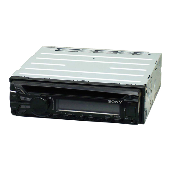
Photo: CDX-GT470UM
Model Name Using Similar Mechanism
Mechanism Type
Optical Pick-up Name
SPECIFICATIONS
Tuner section
(Russian model)
FM
Tuning range:
CDX-GT472UE/CDX-GT470UE
FM1/FM2: 87.5 – 108.0 MHz (at 50 kHz step)
FM3: 65 – 74 MHz (at 30 kHz step)
CDX-GT470UM
Tuning range: 87.5 – 108.0 MHz
Antenna (aerial) terminal:
External antenna (aerial) connector
Intermediate frequency: 25 kHz
Usable sensitivity: 8 dBf
Selectivity: 75 dB at 400 kHz
Signal-to-noise ratio: 80 dB (stereo)
Separation: 50 dB at 1 kHz
Frequency response: 20 – 15,000 Hz
MW/LW
Tuning range:
MW: 531 – 1,602 kHz
LW: 153 – 279 kHz
Antenna (aerial) terminal:
External antenna (aerial) connector
Intermediate frequency:
9,124.5 kHz or 9,115.5 kHz/4.5 kHz
Sensitivity: MW: 26 μV, LW: 45 μV
Tuner section
(E, Mexican, Argentina, Korean
and Indian models)
FM
Tuning range:
For non-Argentine models:
87.5 – 108.0 MHz (at 50 kHz step)
87.5 – 108.0 MHz (at 100 kHz step)
87.5 – 107.9 MHz (at 200 kHz step)
For Argentine models:
87.5 – 107.9 MHz
FM tuning step (for non-Argentine models):
US, Canadian, E, Mexican, Argentina, Korean and Indian models
50 kHz/100 kHz/200 kHz switchable
Antenna (aerial) terminal:
External antenna (aerial) connector
Intermediate frequency: 25 kHz
Usable sensitivity: 8 dBf
Selectivity: 75 dB at 400 kHz
Signal-to-noise ratio: 80 dB (stereo)
Separation: 50 dB at 1 kHz
Frequency response: 20 – 15,000 Hz
AM
Tuning range:
For non-Argentine models:
531 – 1,602 kHz (at 9 kHz step)
530 – 1,710 kHz (at 10 kHz step)
For Argentine models:
530 – 1,710 kHz
AM tuning step (for non-Argentine models):
9 kHz/10 kHz switchable
Antenna (aerial) terminal:
External antenna (aerial) connector
Intermediate frequency:
For non-Argentine models:
9,124.5 kHz or 9,115.5 kHz/4.5 kHz
(at 9 kHz step)
9,115 kHz or 9,125 kHz/5 kHz
(at 10 kHz step)
For Argentine models:
9,115 kHz or 9,125 kHz/5 kHz
Sensitivity: 26 μV
CDX-GT470UM/GT472UM/GT474UM
CDX-GT470UE/GT470UM/GT472UE
Tuner section
USB Player section
(Saudi Arabia model)
Interface: USB (Full-speed)
Maximum current: 1 A
FM
Tuning range:
Power amplifier section
87.5 – 108.0 MHz
Antenna (aerial) terminal:
Output: Speaker outputs
External antenna (aerial) connector
Speaker impedance: 4 – 8 ohms
Maximum power output: 52 W × 4 (at 4 ohms)
Intermediate frequency: 25 kHz
Usable sensitivity: 8 dBf
Selectivity: 75 dB at 400 kHz
General
Signal-to-noise ratio: 80 dB (stereo)
Outputs:
Separation: 50 dB at 1 kHz
Audio outputs terminal (rear/sub switchable)
Frequency response: 20 – 15,000 Hz
Power antenna (aerial)/Power amplifier control
terminal (REM OUT)
MW
Inputs:
Tuning range:
Remote controller input terminal
531 – 1,602 kHz
Antenna (aerial) input terminal
Antenna (aerial) terminal:
AUX input jack (stereo mini jack)
External antenna (aerial) connector
USB port
Intermediate frequency:
Power requirements: 12 V DC car battery
9,124.5 kHz or 9,115.5 kHz/4.5 kHz
(negative ground (earth))
Sensitivity: 26 μV
Dimensions: Approx. 178 × 50 × 177 mm
SW
1
× 2 × 7 in) (w/h/d)
(7
/
8
Tuning range:
Mounting dimensions: Approx. 182 × 53 × 160 mm
1
× 2
1
SW1: 2,940 – 7,735 kHz
(7
/
/
4
8
SW2: 9,500 – 18,135 kHz
Mass: Approx. 1.2 kg (2 lb 11 oz)
(except for 10,140 – 11,575 kHz)
Supplied accessories:
Antenna (aerial) terminal:
Remote commander: RM-X211
External antenna (aerial) connector
(CDX-52UM/GT470UM: US, Canadian/
Intermediate frequency:
GT472UE/GT520U/GT525U only)
9,124.5 kHz or 9,115.5 kHz/4.5 kHz
Parts for installation and connections (1 set)
Sensitivity: 26 μV
Design and specifications are subject to change
CD Player section
without notice.
Signal-to-noise ratio: 120 dB
Frequency response: 10 – 20,000 Hz
Wow and flutter: Below measurable limit
FM/AM COMPACT DISC PLAYER
FM/MW/LW COMPACT DISC PLAYER
FM/MW/SW COMPACT DISC PLAYER
US Model
Canadian Model
CDX-GT470UM
AEP Model
UK Model
E Model
CDX-GT520U
Russian Model
Indian Model
CDX-GT52UM/GT525U
CDX-GT40U/GT44U/GT45U
MG-101CA-188
DAX-25A
× 6
5
/
in) (w/h/d)
16
AEP, Russian and UK models
Saudi Arabia model
Advertisement
Table of Contents

Related Manuals for Sony CDX-GT470UE


Summarization of Contents
Specifications
Audio Power Specifications
Details on audio power output according to CEA2006 standard.
Tuner Section Specifications
Tuning ranges, frequencies, sensitivity, and selectivity for various models.
CD Player Section Specifications
Signal-to-noise ratio and frequency response for the CD player.
USB Player Section Specifications
Details on the USB interface and maximum current.
Power Amplifier Section Specifications
Output power and speaker impedance for the power amplifier.
General Specifications
Outputs, inputs, power requirements, and physical dimensions.
Servicing Notes
Handling the Optical Pick-Up Block
Precautions for handling the optical pick-up block to prevent electrostatic breakdown.
Laser Diode Emission Check
Safety warning regarding checking laser diode emission to protect eyesight.
Unleaded Solder Information
Characteristics and handling of unleaded solder for circuit boards.
Disassembly Procedure
Disassembly Flow
Step-by-step guide for disassembling the unit.
Mini Fuse and Cover Removal
Procedure for removing the mini fuse and cover.
Sub Panel Block Disassembly
Instructions for removing the sub panel block.
CD Mechanism Deck Disassembly
Procedure for removing the CD mechanism deck (MG-101CA-188).
Main Board Replacement
Instructions for accessing and replacing the main board.
Servo Board Replacement
Instructions for accessing and replacing the servo board.
Chassis (T) Sub Assy Disassembly
Procedure for disassembling the chassis (T) sub assembly.
Roller Arm Assy Disassembly
Procedure for disassembling the roller arm assembly.
Chassis (OP) Assy Disassembly
Procedure for disassembling the chassis (OP) assembly.
Chucking Arm Sub Assy Disassembly
Procedure for disassembling the chucking arm sub assembly.
Sled Motor Assy Disassembly
Procedure for disassembling the sled motor assembly.
Optical Pick-Up Section Disassembly
Procedure for disassembling the optical pick-up section.
Optical Pick-Up Disassembly
Procedure for disassembling the optical pick-up unit.
Diagrams and Schematics
Block Diagram - Servo Section
Block diagram illustrating the servo section connections.
Block Diagram - Main Section
Block diagram illustrating the main section connections.
Block Diagram - Panel, Power Supply Section
Block diagram for panel and power supply sections.
Schematic Diagram - Main Section (1/5)
Detailed schematic for the main board, part 1 of 5.
Schematic Diagram - Main Section (2/5)
Detailed schematic for the main board, part 2 of 5.
Schematic Diagram - Main Section (3/5)
Detailed schematic for the main board, part 3 of 5.
Schematic Diagram - Main Section (4/5)
Detailed schematic for the main board, part 4 of 5.
Schematic Diagram - Main Section (5/5)
Detailed schematic for the main board, part 5 of 5.
Printed Wiring Board - Main Section (1/2) (Except Saudi Arabia)
Component layout for the main board, part 1 of 2 (excl. Saudi Arabia).
Printed Wiring Boards - Main Section (2/2) (Except Saudi Arabia)
Component layout for the main board, part 2 of 2 (excl. Saudi Arabia).
Printed Wiring Board - Main Section (1/2) (Saudi Arabia Model)
Component layout for the main board, part 1 of 2 (Saudi Arabia).
Printed Wiring Boards - Main Section (2/2) (Saudi Arabia Model)
Component layout for the main board, part 2 of 2 (Saudi Arabia).
Printed Wiring Board - Key Board
Component layout for the key board.
Schematic Diagram - Key Board
Schematic diagram for the key board.
Replacing Lithium Battery
Notes on Lithium Battery
Important notes and warnings regarding lithium battery handling and replacement.
Cleaning Connectors
Connector Cleaning Notes
Important notes for cleaning unit and front panel connectors safely.
General Information
Cautions for General Use
General safety precautions for operating the unit.
Power Supply Lead Notes
Important notes regarding the yellow power supply lead connection.
Connection Examples
Examples of connecting the unit, including subwoofer direct connection.
Connection Diagrams
Diagrams illustrating various connection methods for the unit.
Exploded Views
Main Section Exploded View
Exploded view of the main section with part numbers.
Front Panel Section Exploded View
Exploded view of the front panel section with part numbers.
CD Mechanism Deck Exploded View
Exploded view of the CD mechanism deck (MG-101CA-188).
Electrical Parts List
Key Board Parts
List of electrical parts for the key board.
Miscellaneous Parts
List of miscellaneous electrical parts.
Accessories
List of included accessories.
Installation and Connection Parts
List of parts for installation and connections.
Need help?
Do you have a question about the CDX-GT470UE and is the answer not in the manual?
Questions and answers