
Related Manuals for Carrier TOSHIBA MMK-UP0181HP-UL


Summarization of Contents
Definition of Qualified Installer or Qualified Service Person
Installer Qualifications and Knowledge
Details qualifications for installing, maintaining, relocating, and removing air conditioners.
Service Person Qualifications and Knowledge
Details qualifications for installing, repairing, maintaining, relocating, and removing air conditioners.
Precautions for Safety
DANGER - General Safety Warnings
Highlights critical safety warnings related to electrical hazards and operational safety.
General Safety Precautions
General Safety Advice and Earth Wire Connection
Provides general safety guidelines and specific instructions for earth wire connection.
Safety Instructions and Refrigerant Handling
Prohibitions and Specified Parts Usage
Outlines modifications, parts usage, and specific prohibitions for safe operation.
Refrigerant Handling Cautions
Details critical safety measures for handling R410A refrigerant.
Procedures and Checks
Assembly, Wiring, and Post-Repair Checks
Covers assembly, wiring, insulation checks, and post-repair verification steps.
Installation and Operation Guidance
Installation Considerations
Provides guidelines for unit installation and safe operation.
Relocation Guidance
Offers instructions and warnings for relocating the air conditioner unit.
R410A Refrigerant and Piping
R410A Safety and Installation Cautions
Safety precautions and installation guidelines specific to R410A refrigerant.
Pipe Materials for R410A
Details specifications for copper pipes and joints used with R410A.
Tools for R410A and General Tools
Tools Exclusive for R410A
Lists tools specifically required for R410A system installation and service.
General Tools (Conventional)
Lists common tools that can also be used for R410A and conventional systems.
Parts Rating and Identification
Parts Rating
Details the specifications for various unit components.
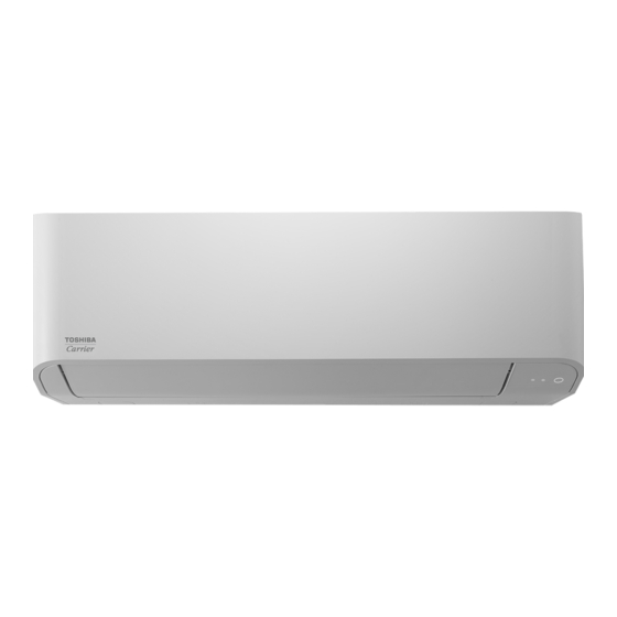
Name of Each Part
Provides a visual identification of the main parts of the indoor unit.
Indoor Unit Control Outline
Power Supply Reset and Operation Select
Describes control behavior after power reset and operation mode selection.
Room Temperature and Air Volume Control
Details temperature control settings and air volume adjustments.
Indoor Unit Control Outline (Continued)
Cold Air Discharge and Freeze Prevention Control
Explains prevention of cold air and freeze control mechanisms.
Indoor Unit Control Outline (Continued)
Refrigerant Recovery and Flap Control
Covers refrigerant recovery operations and flap position control.
Indoor Unit Control Outline (Continued)
Filter Display and Standby Modes
Details filter status display and unit standby modes.
Central Control Mode Selection
Explains how to select modes for central control systems.
Indoor Unit Control Outline (Continued)
Hi POWER and ECO Timer Operations
Describes Hi POWER and ECO timer functions for remote controls.
Indoor Unit Control Outline (Continued)
PRESET, DC Motor, and Save Operations
Details PRESET, DC motor, and Save operation functions.
Indoor Unit Control Outline (Continued)
Secondary Heating Modes
Explains normal and flip modes for secondary heating.
Indoor Unit Control Outline (Continued)
Secondary Heating Configuration
Details configuration codes for secondary heating.
Communication Type and Connectable Units
Communication Type and Model Names
Lists communication types and corresponding model names.
TU2C-Link and TCC-Link Wiring
Describes wiring specifications for TU2C-Link and TCC-Link combinations.
Control Circuit Configuration
Indoor Controller Block Diagram (MCC-1696)
Provides a block diagram of the indoor unit's control circuit.
Wired Remote Controller Connection
Details the connection procedure for wired remote controllers.
Control Circuit Configuration (Continued)
Wireless Remote Controller Connection
Details the connection procedure for wireless remote controllers.
Test Run Functions
Cooling/Heating Test Run Check
Describes how to perform cooling and heating test runs.
Test Run from Indoor Remote Controller
Details the procedure for initiating a test run via the indoor remote controller.
Test Run (Wireless Remote Controller - Forced Operation)
Check Wiring/Piping
Instructions for checking indoor/outdoor unit wiring and piping.
Check Remote Controller Transmission
Procedure to verify remote controller signal transmission.
Applied Control - Indoor Unit Function Setup
Setup of Selecting Function in Indoor Unit
Guides on setting functions for indoor units via remote controller.
Applied Control (Continued)
DN Setting Configuration
Details on configuring DN settings through the Field setting menu.
Applied Control - Remote Location ON/OFF
Wiring and Setup
Instructions for wiring and setting up the ON/OFF control box.
Wiring Diagram (TCB-IFCB-4UL)
Diagram illustrating wiring for the remote control interface.
Ventilating Fan Control from Remote Controller
Function and Operation
Explains the function and operation of ventilating fan control via remote.
Ventilating Fan Control (Continued)
Wiring for Fan Control
Provides wiring details for controlling the ventilating fan.
Auto-Off Feature Control
Function and Setup Method
Details the auto-off function and its setup procedures.
Card Input Setup - Code (DN)
External Contact Terminal Functions
Describes the functionality of external contact terminals for card input.
Notice Code Signal
Function and Setup Method
Explains the notice code function and its setup via DN code.
Manual Address Setting
Wiring Example and Line Address Setup
Illustrates wiring and guides on setting line addresses.
Manual Address Setting (Continued)
Indoor Unit Address Setup
Procedure for setting indoor unit addresses.
Group Address Setup
Procedure for setting group addresses for connected units.
Manual Address Setting (Continued)
Indoor Unit Address Configuration
Details configuration for indoor unit addresses.
Group Address Configuration
Details configuration for group addresses.
Positioning Indoor Units by Address
Procedure for Address Positioning
Steps to determine and set the position of indoor units by address.
Check Code Clearing Function
Clearing Outdoor Unit Check Codes
Procedure to clear check codes detected by the outdoor unit.
Clearing Indoor Unit Check Codes
Procedure to clear check codes detected by the indoor unit.
Check Code Clearing Function (Continued)
Deleting Check Code History
Instructions for deleting recorded check code history.
Troubleshooting
Overview of Troubleshooting
Provides an overview of troubleshooting procedures and general precautions.
Troubleshooting Method
List of Check Codes (Indoor Unit)
Lists check codes detected by the indoor unit and their typical causes.
Troubleshooting - Check Codes by Device
Check Codes from Remote Controller
Lists check codes detected by the remote controller.
Check Codes from Central Control Device
Lists check codes detected by the central control device.
FS Unit Relation Check Codes
Lists check codes related to the Flow Selector (FS) unit.
Troubleshooting by Remote Controller Display
Confirmation and Check
Procedure for checking current errors and confirming system status.
Alarm History Confirmation
How to view and confirm the history of past alarms.
Deleting Alarm History
Instructions for clearing the recorded alarm history.
Troubleshooting - Other Indications & FS Unit
Other Indications (Not Check Codes)
Lists indications that do not involve specific check codes.
FS Unit Relation Check Codes
Troubleshooting codes related to the Flow Selector (FS) unit.
Check Codes - Remote Controller & Outdoor Unit
Check Codes Displayed on Remote Controller
Details check codes shown on the remote controller.
Servicing Compressor and Fan Motor
How to Check Inverter Output
Procedure for checking the inverter output voltage.
How to Check Compressor Winding Resistance
Procedure for measuring compressor winding resistances.
How to Check Outdoor Fan Motor
Procedure for checking the outdoor fan motor and its winding resistance.
Diagnostic Procedures for Check Codes (Indoor Unit)
[E01] Indoor/Remote Controller Communication Trouble
Troubleshooting steps for E01 communication error.
[E02] Remote Controller Transmission Trouble
Troubleshooting steps for E02 remote controller transmission error.
[E03] Indoor/Remote Controller Communication Trouble
Troubleshooting steps for E03 communication error.
Diagnostic Procedures (Continued)
[E04] Indoor/Outdoor Communication Circuit Trouble
Troubleshooting steps for E04 indoor/outdoor communication circuit error.
[E08] Duplicated Indoor Addresses
Troubleshooting steps for E08 duplicated indoor address error.
Diagnostic Procedures (Continued)
[E09] Duplicated Header Remote Controller
Troubleshooting steps for E09 duplicated header remote controller.
[E10] Communication Trouble between Indoor MCUs
Troubleshooting steps for E10 communication trouble between MCUs.
[E11] Communication Trouble between Application Control Kit and Indoor Unit
Troubleshooting steps for E11 communication trouble.
Diagnostic Procedures (Continued)
[E18] Communication Trouble between Indoor Header and Follower
Troubleshooting steps for E18 communication trouble between header/follower units.
[F01] Indoor TCJ Sensor Trouble
Troubleshooting steps for F01 TCJ sensor error.
[F02] Indoor TC2 Sensor Trouble
Troubleshooting steps for F02 TC2 sensor error.
Diagnostic Procedures (Continued)
[F03] Indoor TC1 Sensor Trouble
Troubleshooting steps for F03 TC1 sensor error.
[F10] Indoor TA/TSA Sensor Trouble
Troubleshooting steps for F10 TA/TSA sensor error.
[F29] Indoor Other Trouble
Troubleshooting steps for F29 general indoor unit errors.
[F30] Occupancy Sensor Trouble
Troubleshooting steps for F30 occupancy sensor error.
Diagnostic Procedures (Continued)
[L07] Group Line Connected to Individual Unit
Troubleshooting for L07 group line connected to individual unit.
[L03] Duplicated Indoor Header Units
Troubleshooting for L03 duplicated indoor header units.
[L08] Indoor Unit Address Unset
Troubleshooting for L08 unset indoor unit address.
[L20] Duplicated Central Control Addresses
Troubleshooting for L20 duplicated central control addresses.
[L09] Indoor Unit Capacity Unset
Troubleshooting for L09 unset indoor unit capacity.
Diagnostic Procedures (Continued)
[L30] Abnormal Input from Outside
Troubleshooting for L30 abnormal external input.
[P10] Water Overflow in Indoor Unit
Troubleshooting for P10 indoor unit water overflow.
Diagnostic Procedures (Continued)
[P12] Indoor Fan Motor Trouble
Troubleshooting steps for P12 indoor fan motor issues.
[P31] Other Indoor Trouble (Group Follower Unit)
Troubleshooting for P31 issues in group follower units.
Sensor Characteristics - Indoor Unit
Indoor TA Sensor Characteristics
Temperature vs. resistance characteristics for the TA sensor.
Indoor TC1 Sensor Characteristics
Temperature vs. resistance characteristics for the TC1 sensor.
Indoor TC2 and TCJ Sensors Characteristics
Temperature vs. resistance for TC2 and TCJ sensors.
Replacement of Service P.C. Board - Indoor Unit
Replacement Procedures - CASE 1
Steps for replacing the P.C. board when EEPROM data is readable.
Replacement Procedures - CASE 2
Steps for replacing P.C. board when EEPROM data is not readable.
Writing Setting Data to EEPROM
Change of Lighting Time of Filter Sign
Procedure to adjust filter sign lighting time.
To Secure Better Effect of Heating
Methods to improve heating performance.
Changing the Wind Direction
Instructions for adjusting horizontal louvers and wind direction.
P.C. Board Replacement Procedures
Single Operation Setup
Procedure for replacing P.C. board in single unit operation.
Group Operation Setup
Procedure for replacing P.C. board in group operation.
Writing Setting Data to EEPROM (Continued)
Change of Lighting Time of Filter Sign
Procedure to adjust filter sign lighting time.
To Secure Better Effect of Heating
Methods to improve heating performance.
Changing the Wind Direction
Instructions for adjusting horizontal louvers and wind direction.
Configuration Data Tables
Table 1. Setting Data (CODE No. table)
Provides examples of setting data for various CODE Nos.
Table 2. Type : CODE NO.10
Maps unit types to CODE NO. 10 settings.
Table 3. Indoor unit capacity : CODE No.11
Maps indoor unit capacities to CODE NO. 11 settings.
Installation Manual
Precautions for Safety
Safety guidelines to follow before installing the air conditioner.
Accessory Parts
Lists all included accessory parts for installation.
Selection of Installation Place
Guidance on choosing an appropriate location for installation.
Precautions for Safety
General Safety Precautions
General safety rules to ensure safe installation and operation.
Precautions for Safety (Continued)
Installation Location Selection
Guidelines for selecting safe installation locations.
Installation Steps
Instructions for securely installing the air conditioner unit.
Precautions for Safety (Continued)
Refrigerant Piping Safety
Safety measures for installing refrigerant piping.
Electrical Wiring Safety
Safety measures for electrical wiring and grounding.
Precautions for Safety (Continued)
Test Run Safety
Safety checks before and after performing a test run.
User Guidance on Safety
Information to provide to the user regarding safety.
Relocation and New Refrigerant Installation
Relocation Precautions
Safety warnings and procedures for relocating the unit.
R410A Installation Precautions
Specific precautions for installing units using R410A refrigerant.
Selection of Installation Place
Avoid Installing in These Locations
Lists locations to avoid for proper installation and unit performance.
Installation Diagrams and Space Requirements
Installation Space Requirements
Specifies required clearances for installation and service.
Installation Place Criteria
Defines ideal conditions and locations for unit installation.
Indoor Unit Installation
Wireless Remote Controller Location
Guidance on optimal placement for the wireless remote controller.
Electrical Cover Installation
Removing Electrical Cover
Steps for safely removing the electrical cover.
Installing Electrical Cover
Steps for correctly installing the electrical cover.
Cutting Hole and Mounting Installation Plate
Cutting the Hole for Piping
Instructions for drilling holes for refrigerant pipes.
Mounting the Installation Plate
Procedure for securely mounting the installation plate.
Piping and Drain Hose Installation
Piping and Drain Hose Forming
Guidance on forming and insulating refrigerant pipes and drain hoses.
Piping and Drain Hose Installation (Continued)
Drains Cap Removal and Fixing
Steps for removing and fixing the drains cap.
Piping and Drain Hose Installation (Continued)
Bottom Right/Left Piping
Instructions for piping connections at the bottom right or left.
Left-Hand Connection Piping
Guidelines for bending and connecting pipes for left-hand connections.
Indoor Unit Fixing and Drainage
Indoor Unit Fixing Procedure
Steps for securely hooking and fixing the indoor unit.
Drainage Installation
Instructions for proper drain hose routing and connection.
Refrigerant Piping
Piping Work Points and Size
Key piping work points, dimensions, and permissible lengths.
Permissible Piping Length and Height
Details varying piping length and height differences based on outdoor unit.
Refrigerant Piping (Continued)
Tightening Connection and Insulation
Guidelines for tightening connections and insulating pipes.
Airtight Test and Air Purge
Procedures for airtight testing, air purging, and gas leak checks.
Electrical Connection
Power Supply and Control Wire Specs
Specifications for power supply and control wiring.
Control Wiring Details
Information on control wiring and central control wiring.
Electrical Connections (Continued)
Power Supply Wire Specifications
Recommended wire diameter and length for power supply wire.
Communication Line Types
Details communication types and corresponding model names.
Wiring Details for SMMS-u Series
Uv/Uc and Uh Line Specifications
Wiring specifications for Uv/Uc and Uh lines in SMMS-u systems.
Control Wiring Specifications
Specifications for control wiring between units.
Wiring Details for SMMS-u Series (Continued)
Remote Control Wiring
Details on wiring for remote control and group control.
Connectable Units and Wiring
Max. Units & Communication Types
Table showing max connectable units and communication types.
Indoor/Outdoor Unit Wiring Example
Diagram illustrating wiring between indoor and outdoor units.
Address Setup and Wired Remote Controller Wiring
Address Setup Procedure
Steps for setting unit addresses as per outdoor unit manual.
Wired Remote Controller Wiring Diagram
Diagram showing wiring connections for wired remote controllers.
Wiring Connection - Power and Control Wires
Connecting Power Supply and Control Wires
Procedure for connecting power supply and control wires without removing front panel.
Wiring Connection for Flow Selector Unit
Connecting Flow Selector Unit Wiring
Instructions for connecting power and communication wires for flow selector unit.
Applicable Controls
Basic Procedure for Changing Settings
General steps for changing unit settings via remote controller.
Applicable Controls (Continued)
Change of Lighting Time of Filter Sign
Procedure to adjust filter sign lighting time.
To Secure Better Effect of Heating
Methods to improve heating performance.
Changing the Wind Direction
Instructions for adjusting horizontal louvers and wind direction.
Applicable Controls (Continued)
Cancelling Swing Operation
Procedure to cancel swing operation for louvers.
Group Control Operation
Details on controlling multiple units in a group.
Remote Controller Sensor Function
Explanation of using the remote controller sensor for temperature.
Test Run
Before Test Run Procedures
Safety checks and preparation steps before performing a test run.
Executing a Test Run
Procedure for executing a test run using the remote controller.
Test Run (Wireless Remote Controller - Forced Operation)
Check Wiring/Piping
Instructions for checking indoor/outdoor unit wiring and piping.
Check Remote Controller Transmission
Procedure to verify remote controller signal transmission.
Troubleshooting
Confirmation and Check
Procedure for checking current errors and confirming system status.
Alarm History Confirmation
How to view and confirm the history of past alarms.
Deleting Alarm History
Instructions for clearing the recorded alarm history.
Check Method and Code List
Check Method Overview
Explains how to use the check code list for diagnosis.
Check Code List
Comprehensive list of check codes and their meanings.
Troubleshooting - Inverter and Central Control
*1 Inverter Quantity Information
Information regarding inverter quantity for SMMS systems.
Trouble Detected by Central Control Device
Lists troubles detected by the central control device.
Warnings on Refrigerant Leakage
Check of Concentration Limit
Specifies concentration limits for refrigerant gas in rooms.
Confirmation of Indoor Unit Setup
Indoor Unit Setup Check Sheet
A checklist for confirming indoor unit setup after installation.
How to Replace Main Parts - Indoor Unit
Air Inlet Grille Replacement
Procedure for removing and reinstalling the air inlet grille.
How to Replace Main Parts (Continued)
Air Filters Replacement
Procedure for removing and replacing air filters.
Front Panel Replacement
Procedure for removing and reinstalling the front panel.
How to Replace Main Parts (Continued)
Electric Part Box Assembly Replacement
Procedure for replacing the electric part box assembly.
How to Replace Main Parts (Continued)
Fan Motor Replacement
Procedure for removing and replacing the fan motor.
Horizontal Louver Replacement
Procedure for removing and replacing the horizontal louver.
Drain Hose Replacement
Procedure for removing and reinstalling the drain hose.
How to Replace Main Parts (Continued)
Drain Pan Assembly Replacement
Procedure for removing and replacing the drain pan assembly.
How to Replace Main Parts (Continued)
Vertical Louver Assembly Replacement
Procedure for removing and replacing the vertical louver assembly.
Cover Motor VT Assembly Replacement
Procedure for removing and replacing the cover motor VT assembly.
Bearing Base Replacement
Procedure for removing and replacing the bearing base.
Cross Flow Fan Replacement
Procedure for removing and replacing the cross flow fan.
How to Replace Main Parts (Continued)
Heat Exchanger (Evaporator) Replacement
Procedure for removing and replacing the heat exchanger.
Need help?
Do you have a question about the TOSHIBA MMK-UP0181HP-UL and is the answer not in the manual?
Questions and answers