Table of Contents
Advertisement
+001111053901_00Ta.book Page 1 Monday, January 17, 2011 11:35 AM
AIR CONDITIONER (MULTI TYPE)
Installation Manual
Indoor Unit
Model name:
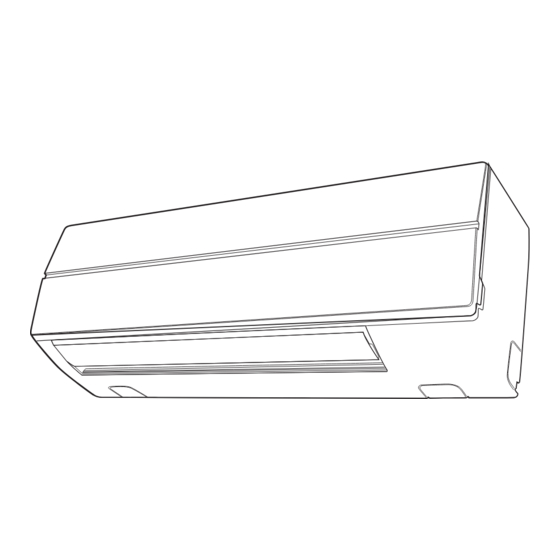
High Wall Type
MMK-AP0073H2UL
MMK-AP0093H2UL
MMK-AP0123H2UL
MMK-AP0153H2UL
MMK-AP0183H2UL
MMK-AP0243H2UL
Installation Manual
Manuel d'installation
32
English
1
Français
Advertisement
Table of Contents

Related Manuals for Carrier MMK-AP0073H2UL


Summary of Contents for Carrier MMK-AP0073H2UL
-
Page 1: Installation Manual
+001111053901_00Ta.book Page 1 Monday, January 17, 2011 11:35 AM AIR CONDITIONER (MULTI TYPE) Installation Manual Indoor Unit Model name: High Wall Type MMK-AP0073H2UL MMK-AP0093H2UL MMK-AP0123H2UL MMK-AP0153H2UL MMK-AP0183H2UL MMK-AP0243H2UL English Installation Manual Manuel d’installation Français... -
Page 2: Table Of Contents
+001111053901_00Ta.book Page 1 Monday, January 17, 2011 11:35 AM Installation Manual High Wall Type Please read this Installation Manual carefully before installing the Air Conditioner. • This Manual describes the installation method of the indoor unit. • For installation of the outdoor unit, refer to the Installation Manual attached to the outdoor unit. ADOPTION OF NEW REFRIGERANT This Air Conditioner uses R410A an environmentally friendly refrigerant. -
Page 3: Accessory Parts
+001111053901_00Ta.book Page 2 Monday, January 17, 2011 11:35 AM Installation Manual High Wall Type Accessory Parts Accessory parts Part name Q’ty Shape Installation plate Wireless remote control Battery Remote control holder Mounting screw Ø0.16” (4 mm) × 1.0” (25 mm) Pan head wood screw Ø1/8”... -
Page 4: Precautions For Safety
+001111053901_00Ta.book Page 3 Monday, January 17, 2011 11:35 AM Installation Manual High Wall Type Precautions for Safety Installing, starting up, and servicing air-conditioning equipment can be hazardous due to system pressures, electrical components, and equipment location (roofs, elevated structures, etc.). Only trained, qualified installers and service mechanics should install, start-up, and service this equipment. - Page 5 +001111053901_00Ta.book Page 4 Monday, January 17, 2011 11:35 AM Installation Manual High Wall Type • If refrigerant gas has leaked during the installation work, ventilate the room immediately. If the leaked refrigerant gas comes in contact with fire, noxious gas may generate. •...
-
Page 6: Selection Of Installation Place
+001111053901_00Ta.book Page 5 Monday, January 17, 2011 11:35 AM Installation Manual High Wall Type Selection of Installation Place WARNING • Install the air conditioner securely in a location where the base can sustain the weight adequately. If the strength is not enough, the unit may fall down resulting in injury. CAUTION •... -
Page 7: Installation Diagram Of Indoor And Outdoor Units
+001111053901_00Ta.book Page 6 Monday, January 17, 2011 11:35 AM Installation Manual High Wall Type Installation diagram of Indoor and outdoor units Before installing the wireless remote Hook control For the rear left and left piping 1.Remove the battery Installation plate cover. -
Page 8: Wireless Remote Control
+001111053901_00Ta.book Page 7 Monday, January 17, 2011 11:35 AM Installation Manual High Wall Type Wireless remote control • A place where there are no obstacles such as a curtain that may block the signal from the indoor unit. • Do not install the remote control in a place exposed to direct sunlight or close to a heating source, such as a stove. - Page 9 +001111053901_00Ta.book Page 8 Monday, January 17, 2011 11:35 AM Installation Manual High Wall Type Cutting a hole and mounting When the installation plate is directly mounted on the wall installation plate 1. Securely fit the installation plate onto the wall by screwing it in the upper and lower Cutting a hole parts to hook up the indoor unit.
-
Page 10: Drain Piping Work
+001111053901_00Ta.book Page 9 Monday, January 17, 2011 11:35 AM Installation Manual High Wall Type Drain Piping Work Piping and drain hose forming * Apply heat-insulation for both refrigerant pipe and drain hose surely so that no dew generates inside of the equipment. - Page 11 +001111053901_00Ta.book Page 10 Monday, January 17, 2011 11:35 AM Installation Manual High Wall Type Remove the drains cap Clip the drain cap by needle-nose pliers and pull out. Fix the drains cap 1) Insert a 4 mm hexagonal wrench in a centre head. 4 mm 2) Firmly insert drains cap.
- Page 12 +001111053901_00Ta.book Page 11 Monday, January 17, 2011 11:35 AM Installation Manual High Wall Type ▼ Bottom right or bottom left piping • After scribing slits of the front panel with a knife or a marking-off pin, cut them with a pair of nippers or an equivalent tool.
-
Page 13: Indoor Unit Fixing
+001111053901_00Ta.book Page 12 Monday, January 17, 2011 11:35 AM Installation Manual High Wall Type Indoor Unit Fixing Drainage 1. Pass the pipe through the hole in the wall, 1. Run the drain hose sloped downwards. and hook the indoor unit on the installation NOTE plate at the upper hooks. -
Page 14: Refrigerant Piping
+001111053901_00Ta.book Page 13 Monday, January 17, 2011 11:35 AM Installation Manual High Wall Type Refrigerant Piping Refrigerant Piping Permissible Piping Length and Height Difference 1. Use copper pipe with 0.03” (0.8 mm) or more thickness. (In case pipe size is dia. They vary according to the outdoor unit. -
Page 15: Tightening Connection
+001111053901_00Ta.book Page 14 Monday, January 17, 2011 11:35 AM Installation Manual High Wall Type Leak check test, evacuation and Tightening connection other procedure CAUTION For leak check test, evacuation, addition of • Do not apply excessive torque. Otherwise, the refrigerant, and gas leak check, refer to the nut may crack depending on the conditions. - Page 16 +001111053901_00Ta.book Page 15 Monday, January 17, 2011 11:35 AM Installation Manual High Wall Type Wireless remote control A-B NOTE selection • Repeat above step to reset wireless remote To use 2 wireless remote controls for the respective control to be A. air conditioners, when the 2 air conditioners are •...
-
Page 17: Electrical Connection
+001111053901_00Ta.book Page 16 Monday, January 17, 2011 11:35 AM Installation Manual High Wall Type Electrical Connection REQUIREMENT WARNING • For power supply wiring, strictly conform to the 1. Use predefined wire and connect them Local Regulation in each country. certainly. Keep the connecting terminal •... -
Page 18: Electric Characteristics
1 × AWG12 or thicker Ground Electric characteristics MCA : Minimum Circuit Amps MOCP : Maximum Overcurrent Protection (Amps) Voltage Range (V) MOCP Model Power Supply MMK-AP0073H2UL MMK-AP0093H2UL MMK-AP0123H2UL 208/230V-1-60Hz MMK-AP0153H2UL MMK-AP0183H2UL MMK-AP0243H2UL Control wire Control wiring between indoor units, and outdoor (Up to 3280’10”... -
Page 19: Wiring Between Indoor And Outdoor Units
+001111053901_00Ta.book Page 18 Monday, January 17, 2011 11:35 AM Installation Manual High Wall Type Wiring between indoor and outdoor units NOTE An outdoor unit connected with control wiring between indoor and outdoor units wire becomes automatically the header unit. ▼ Wiring example Outdoor Power supply Outdoor Power supply 208/230-3-60... -
Page 20: Wire Connection
+001111053901_00Ta.book Page 19 Monday, January 17, 2011 11:35 AM Installation Manual High Wall Type Wire Connection Terminal block for wired remote control/control REQUIREMENT wiring • Connect the wires matching the terminal Ground screw for numbers. shielded wire Control Incorrect connection causes a trouble. wire •... -
Page 21: Address Setup
+001111053901_00Ta.book Page 20 Monday, January 17, 2011 11:35 AM Installation Manual High Wall Type 5. Clamp the wires with the cord clamp. 12.Attach the conduit cover. 6. Install the clamp base with a screw. 13.Attach the terminal cover, the front panel and the air inlet grille to the indoor unit. -
Page 22: Applicable Controls
+001111053901_00Ta.book Page 21 Monday, January 17, 2011 11:35 AM Installation Manual High Wall Type Applicable Controls A wired remote control is necessary for this function. This function cannot be operate with a wireless remote control. Changing applicable control REQUIREMENT setting •... -
Page 23: Filter Sign Setting
+001111053901_00Ta.book Page 22 Monday, January 17, 2011 11:35 AM Installation Manual High Wall Type Filter sign setting Procedure Each time button is pushed, indoor unit According to the installation condition, the lighting numbers in the control group change cyclically. time of the filter sign (Notification of filter cleaning) Select the indoor unit to change settings for. -
Page 24: Adjustment Of Air Direction
+001111053901_00Ta.book Page 23 Monday, January 17, 2011 11:35 AM Installation Manual High Wall Type Adjustment of air direction 1. Using the remote control, change the up/ down air direction by moving the horizontal louver. 2. Adjust the right/left air direction by bending the vertical grille inside of the air outlet port with hands. -
Page 25: Test Run
+001111053901_00Ta.book Page 24 Monday, January 17, 2011 11:35 AM Installation Manual High Wall Type Test Run ▼ In case of wired remote control Before test run • Before turning on the circuit breaker, carry out Procedure the following procedure. 1) By using 500V-megger, check that resistance Push button. - Page 26 +001111053901_00Ta.book Page 25 Monday, January 17, 2011 11:35 AM Installation Manual High Wall Type ▼ In case of wireless remote control (Forced test operation is performed in a different way.) REQUIREMENT • For the operation procedure, be sure to follow the Owner’s Manual.
-
Page 27: Troubleshooting
+001111053901_00Ta.book Page 26 Monday, January 17, 2011 11:35 AM Installation Manual High Wall Type Troubleshooting A wired remote control is necessary for this function. This function cannot be operate with a wireless remote control. Confirmation and check Procedure Push button. The error log stored in When an error occurred in the air conditioner, the memory is displayed in order. -
Page 28: Check Code List
+001111053901_00Ta.book Page 27 Monday, January 17, 2011 11:35 AM Installation Manual High Wall Type Check codes and parts to be checked Check method On the remote control (Wired remote control, Central control remote control) and the interface P.C. board of the outdoor unit (I/F), a check display LCD (Remote control) or 7-segment display (on the outdoor interface P.C. - Page 29 +001111053901_00Ta.book Page 28 Monday, January 17, 2011 11:35 AM Installation Manual High Wall Type Check code Wireless remote control Wired Sensor block display of Judging Outdoor 7-segment display Check code name remote receiving unit device control Operation Timer Ready Flash Auxiliary code display E28 Detected outdoor unit number...
- Page 30 +001111053901_00Ta.book Page 29 Monday, January 17, 2011 11:35 AM Installation Manual High Wall Type Check code Wireless remote control Wired Sensor block display of Judging Outdoor 7-segment display Check code name remote receiving unit device control Operation Timer Ready Flash Auxiliary code display —...
- Page 31 I/F Differs according to error contents of unit with occurrence of alarm Group control branching unit error TCC-LINK — — (L20 is displayed) Duplicated central control addresses TCC-LINK : TOSHIBA Carrier Communication Link. – 30 – 30-EN...
- Page 32 +001111053901_00Ta.book Page 31 Monday, January 17, 2011 11:35 AM Installation Manual High Wall Type WARNINGS ON REFRIGERANT LEAKAGE Check of Concentration Limit Important The room in which the air conditioner is to be NOTE 2 : installed requires a design that in the event of The standards for minimum room volume are as follows.
- Page 33 +001111053901_00Ta.book Page 33 Monday, January 17, 2011 11:35 AM Confirmation of Indoor Unit Setup Prior to delivery to the customer, check the address and setup of the indoor unit, which has been installed in this time and fill the check sheet (Table below). Data of four units can be entered in this check sheet. Copy this sheet according to the No.
Need help?
Do you have a question about the MMK-AP0073H2UL and is the answer not in the manual?
Questions and answers