Table of Contents
Advertisement
Quick Links
Advertisement
Table of Contents

Related Manuals for Karl Storz TP101


Summary of Contents for Karl Storz TP101
- Page 1 Instructions for use TELE PACK +...
- Page 2 08-2022 Copyright © All product illustrations, product descriptions, and texts are the intellectual property of KARL STORZ SE & Co. KG. Their use and reproduction by third parties require the express approval of KARL STORZ SE & Co. KG. All rights reserved.
-
Page 3: Table Of Contents
Table of contents Table of contents 1 General information ..........................1.1 Read the instructions for use ..................... 1.2 Read the instructions for use of compatible products ............... 1.3 Scope ............................1.4 General signs and symbols ......................1.5 Description of warning messages ....................2 Normal use ............................2.1 Intended use ... - Page 4 Table of contents 6 Application ............................29 6.1 Switching the product on and off ....................29 6.2 Camera head buttons ........................ 29 6.3 Keyboard and mouse ......................... 29 6.4 User interface ..........................29 6.5 Quick menu configuration ......................31 6.6 Connected accessories ......................32 6.6.1 Camera head and videoendoscope ................
- Page 5 Table of contents 10.1 Troubleshooting ......................... 51 11 Overview of mitigating warnings ......................52 12 Subsidiaries ............................53 Instructions for use • TELE PACK + • CQH848_EN_V2.0_08-2022_IFU_CE-MDR...
-
Page 6: General Information
General information 1 General information 1.1 Read the instructions for use If the instructions for use are not followed, patients, users, and third parties may be injured or the product may be damaged. Read the instructions for use carefully and follow all the safety notes and warnings. Read the reprocessing instructions carefully and follow all the safety notes and warnings. -
Page 7: Description Of Warning Messages
General information – Unnumbered list, 2nd level 1.5 Description of warning messages To prevent any injury to persons or damage to property, the warnings and safety notes in the instructions for use must be observed. The warnings use the following levels of danger: WARNING WARNING Designates a possible imminent risk. -
Page 8: Normal Use
Normal use 2 Normal use 2.1 Intended use The TELE PACK + is a combination device comprising a light source for illumination, camera control unit for image processing and documentation, as well as a monitor for visualization. It is designed for endoscopic diagnostic and surgical procedures as well as for stroboscopy. -
Page 9: Safety And Warning
Safety and warning 3 Safety and warning WARNING Danger due to non-observance of warnings and safety notes This chapter contains warnings and safety notes structured according to hazards and risks. 1. Carefully read and observe all warnings and safety notes. 2. -
Page 10: Dangers From Electrical Current
Safety and warning Only use devices and components that have standardized interfaces and do not breach the normal use of the product. 3.5 Dangers from electrical current An improper power supply may cause an electric shock and injure patients, users, or third parties. Use either the power cord supplied by KARL STORZ or a power cord which has the same properties and which bears a national mark of conformity. -
Page 11: Observing Ambient Conditions
Safety and warning Have a replacement product ready for each application or plan for an alternative surgical technique. 3.10 Observing ambient conditions If the device is stored, transported, operated or reprocessed under unsuitable conditions, patients, users or third parties may be injured and the device can be damaged. Observe the ambient conditions listed in the instructions for use and reprocessing. -
Page 12: Product Description
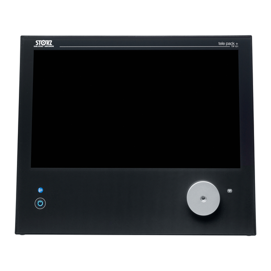
Product description 4 Product description 4.1 Product overview TELE PACK + (TP101) – front view Touch screen Camera connection 2: X-Line USB 2.0 (2x) Lateral connection area Connection for stroboscopy microphone Light connection Camera connection: 1 C-Line ON/OFF button TELE PACK + (TP101) – rear view Carrying handle Mains socket Speaker/headphone connection... -
Page 13: Possible Combinations
Product description USB 2.0 (4x) Cable manager Network socket Mount for camera head holder Kensington lock slot 4.2 Possible combinations It is recommended that the suitability of the products for the intended procedure be checked prior to use. Please note that the products listed here may not yet be available in all countries due to differences in approval requirements. - Page 14 Product description Item Order no. Flexible HD video cystoscope 11272VHU Video bronchoscope 11900BP Video bronchoscope HD 11910T Video bronchoscope HD 11910D Video bronchoscope 11910P Video bronchoscope 11910S Video choledochoscope 11292VP Video choledochoscope 11292VPU Video choledochoscope 11292VS Video choledochoscope 11292VSU Veterinary videoendoscope 60278VS Veterinary videoendoscope 60278VSU...
-
Page 15: Technical Data
Product description Item Order no. Video Esophagoscope 13303E FIVE S 3.5x65, sterile, for single use 091361-01 FIVE S 5.3x65, sterile for single use 0915612-01 CMOS Video Esophagoscope SSU 091370-01 CMOS Video Rhino-Laryngoscope SSU 091330-01 CMOS Video Cysto-Urethroscope 11272VE CMOS Video Cysto-Urethroscope 11272VUE CMOS Video Cystoscope-Urethroscope (US 11272VUE-R... -
Page 16: Symbols Employed
Product description Description Value Video interface 1x DVI-D Audio 3.5 mm jack (in/out – rear), KARL STORZ stro- boscopy microphone (1 x lateral) Footswitch connection Printer connection Printer languages PostScript 4.4 Symbols employed 4.4.1 Symbols on the packaging Symbol Meaning Manufacturer Date of manufacture Medical device Article no. -
Page 17: Symbols On The Product
Product description Symbol Meaning Humidity limit Federal (USA) law restricts this device to sale by or on the order of a physician. CE marking With this marking, the manufacturer declares the conformity of the product with the applicable EU directives. A code number after the CE mark indicates the responsible notified body. -
Page 18: Symbols On The Type Plate
Product description Symbol Meaning Microphone input Lateral stroboscopy microphone input Hot surface 4.4.3 Symbols on the type plate Symbol Meaning Manufacturer Date of manufacture Medical device Article no. Federal (USA) law restricts this device to sale by or on the order of a physician. Separate collection of electrical and electronic devices. -
Page 19: Symbols On The User Interface
Product description 4.4.4 Symbols on the user interface Symbol Meaning Full screen Displays the endoscopy image in full screen mode (the user interface no longer appears). White balance Performs white balance. Freeze Freezes the image. During this time, the live image is shown in the top right- hand corner of the monitor. - Page 20 Product description Symbol Meaning Video recording Starts or stops a video recording. Training mode Displays a circle in the center of the image. Training mode can be used specifi- cally for endoscopy training. Camera brightness Sets the brightness of the camera. Print Immediately prints all images in the print queue.
- Page 21 Product description Symbol Meaning Patient management Manages the settings for handling patient data. Module information Calls up the all the necessary information on the system and the connected camera heads and videoendoscopes. Quick menu settings Configures the Quick menu. Network settings Specifies the settings and the user-defined storage location.
- Page 22 Product description Symbol Meaning Video viewing Shows a recorded video. The video does not correspond to the live image. Network connection active Network connection disconnected Camera Footswitch Printer USB storage Internal storage Adds new functions to the Quick menu. Moves the selected function upward in the Quick menu. Instructions for use •...
-
Page 23: Ambient Conditions
Product description Symbol Meaning Pressing the Delete button removes the selected function from the Quick menu. Pressing the Replace button replaces the selected function with a different function. Moves the selected function downward in the Quick menu. 4.5 Ambient conditions Storage and transport conditions Temperature -18°C ... -
Page 24: Preparation
Preparation 5 Preparation 5.1 Unpacking the product Carefully remove the product and accessories from the packaging. Check the delivery for missing items and possible damage. In the case of damage, hidden defects, and short deliveries, document their nature and extent and contact the manufacturer or supplier immediately. -
Page 25: Connecting The Product
Preparation 5.3 Connecting the product Connect the potential equalization cable. Connect the potential equalization cable to the outlet in the treatment room. Connect the power cord. Push the power plug fully into the power socket. Connect the other end of the power cord to the mains socket. Connect the network cable. -
Page 26: Connecting External Devices
Preparation 5.4 Connecting external devices Connect the required peripheral devices to the USB interfaces. Connect the camera head. Push the connector fully into the respective socket. Connect the microphone cable. Instructions for use • TELE PACK + • CQH848_EN_V2.0_08-2022_IFU_CE-MDR... -
Page 27: Connecting The Light Cable
Preparation Connect an external monitor to the DVI D-video output. 5.5 Connecting the light cable WARNING Hot light connections! Risk of burns! The high level of light intensity produced by the light source may cause the light connections and adjacent components to heat up. This can cause burns to users and third parties. Switch off the light source before changing the light cable. -
Page 28: Functional Test
Preparation Remove the screws on the rear left side of the product using a screwdriver. Place the mount for the camera head holder on the product. Turn the screws into the two holes using a screwdriver. Place the camera head holder on the mount. The holder can be placed in 2 positions to ensure proper function and to stow the holder for transport in case of mobile use. -
Page 29: Application
Application 6 Application 6.1 Switching the product on and off Press and hold the ON/OFF for 2.4 seconds button to start the product. Press and hold the ON/OFF button for 2.4 seconds to switch off the product. 6.2 Camera head buttons All compatible camera heads and X-Line videoendoscopes feature three buttons for retrieving programmed functions and for menu control: –... - Page 30 Application Patient area Function space (access to the Setup menu) Information panel Quick menu Patient area Depending on the configuration, the patient area allows one or several patient data sets to be entered manually or patient data sets to be retrieved and selected from a patient worklist. In order to successfully create a patient, the Last name and (in the case of network storage) the Date of birth fields have to be filled in.
-
Page 31: Quick Menu Configuration
Application 6.5 Quick menu configuration The configuration menu is divided into 3 columns. The functions can be moved, replaced, added, or removed. Up to 8 functions can be added in total. The configuration is saved by restarting the product. Quick Menu Select Function Command To change the configurations, press the Quick Menu button in the Setup menu. -
Page 32: Connected Accessories
Application 6.6 Connected accessories 6.6.1 Camera head and videoendoscope The camera head button assignment is shown true to original. Connect a camera head or videoendoscope. Select the connected device from Connected Devices in the info panel. Press the Settings button to change the button assignment. The camera head button assignment cannot be changed on all videoendoscopes. -
Page 33: Performing A Stroboscopy
Application 6.7 Performing a stroboscopy In stroboscopy mode, the integrated LED light source is activated at the same time as the microphone's audio signal. Voice frequency in hertz (Hz) Volume in decibels (dB) Notation Delta frequency (Δ Hz) in slow motion mode Plug the stroboscopy microphone (20140030) into the microphone input socket on the side. -
Page 34: Viewing Image Material
Application 6.8 Viewing image material After the treatment, recorded images and videos can be viewed before the current treatment is completed. An overview of the recorded images and videos can be found in the patient area. Open the Patient area menu to retrieve the recorded images and videos. Select one of the following options: –... -
Page 35: Memory Functionality
Application Define the password rules. ð The password rules apply to all further passwords. Create a new password. Configure all further settings. The following roles can be selected: – Administrator: Full access to all functions and settings – Operating room personnel: Access to patient data. No access to patient data security or storage medium –... -
Page 36: Patient Data Security
Application Internally stored recordings can be removed from the internal storage only via USB export. If large volumes of data are to be stored, a correspondingly large USB storage medium has to be available. The current status of data transfer can be checked in the information area. 6.10 Patient data security The system does not contain patient data as standard. -
Page 37: Labeling
Application – 30 days – 90 days 6.10.2 Labeling Specify whether the digital recordings or prints are to be labeled with patient information or not. Select one of the following options: – No patient data in the patient folder (selected by default) –... -
Page 38: Fileshare Settings
Application 6.11.2 FileShare settings In order to define the storage location, save the configuration for the server in FileShare mode and in Worklist mode. Press the Connect button to test the configuration. ð The test report confirms successful configuration. ð The network function is activated. FileShare Directory name on the FTP server. -
Page 39: Worklist Settings
Application 6.11.4 Worklist settings If a worklist server is to be used as a user-defined storage location, save the configuration for the server in the Worklist tab. Configure the FTP/FileShare tab and enter the required data. Press the Connect button to test the configuration. ð... -
Page 40: Network Dialog
Application Max. worklist items count Maximum number of entries received. Too high a value can noticeably impact perfor- mance. A maximum value of 1,000 is recom- mended. Device Identity Unique name Hostname/IP address IP address or host name of the worklist server. Port The port number used to reach the worklist server. -
Page 41: Local Settings
Application 6.11.6 Local settings The network configuration is defined on the LAN tab. The configuration is performed automatically via DHCP or manually. Press the Connect button to test the set configuration if the data is entered manually. ð The test report confirms successful configuration. ð... -
Page 42: Maintenance, Servicing, Repairs, And Disposal
Maintenance, servicing, repairs, and disposal 7 Maintenance, servicing, repairs, and disposal 7.1 Maintaining the product If they are not described in more detail here, maintenance activities may only be performed by KARL STORZ or by a company authorized by KARL STORZ. 7.1.1 Maintenance The following maintenance intervals are recommended: Interval Activity... -
Page 43: Disposing Of The Product
Maintenance, servicing, repairs, and disposal Please contact your local KARL STORZ subsidiary or authorized dealer (see the list of subsidiaries). Contaminated devices may not be shipped. To prevent contact infections and airborne infections, products must first be decontaminated. KARL STORZ reserves the right to send back contaminated products. -
Page 44: Accessories And Spare Parts
Accessories and spare parts 8 Accessories and spare parts 8.1 Accessories Not all articles are available in all regions. Article Order no. Videoendoscope adaptor 0° TC001 Videoendoscope adaptor 90° TC013 USB to ACC adaptor TC009 Camera head holder, irrigation bottle holder TP002 ACC connecting cable, to control peripheral devices, length 180 cm 20221070... -
Page 45: Electromagnetic Compatibility
Electromagnetic compatibility 9 Electromagnetic compatibility 9.1 General notes on the operating environment The product is suitable for use in professional healthcare settings. Professional healthcare facilities include physician offices, dental offices, limited care facilities, freestanding surgical centers, freestanding birth centers, multiple treatment facilities, hospitals (emergency rooms, patient rooms, intensive care, surgical rooms, outside the HF-shielded room of an ME system for MRT). - Page 46 Electromagnetic compatibility 9.3 Table 1 – Compliance level for immunity tests Guidelines and manufacturer’s declaration – electromagnetic immunity The product is intended for use in the electromagnetic environment specified below. The user of the product should make sure that it is used in such an environment. Immunity tests EN/IEC 60601 test level Compliance level Electromagnetic envi-...
- Page 47 Electromagnetic compatibility Immunity tests EN/IEC 60601 test level Compliance level Electromagnetic envi- ronment – guidelines * Refer to Table 2 for wireless proximity RF field test levels Immunity to con- 3 V on 150 kHz to 3 V on 150 kHz to ducted distur- 80 MHz 80 MHz bances, induced by 1 kHz 80% AM modula-...
- Page 48 Electromagnetic compatibility 9.5 Table 3 – Test levels for radiated and conducted immunity tests Guidelines and manufacturer’s declaration – electromagnetic immunity The product is intended for use in the electromagnetic environment specified below. The user of the product should make sure that it is used in such an environment. Immunity tests EN/IEC 60601-1-2 test Compliance...
- Page 49 Electromagnetic compatibility Immunity tests EN/IEC 60601-1-2 test Compliance Electromagnetic environ- level level ment – guidelines fixed transmitters, an electromagnetic site survey should be considered. If the measured field strength at the location where the device is used exceeds the above compliance levels, the device should be monitored to ensure proper function.
- Page 50 Electromagnetic compatibility Rated maximum out- Separation distance d [m] according to frequency of transmitter put power of the 150 kHz to 80 MHz 80 MHz to 800 MHz 800 MHz to 2.7 GHz transmitter [W] d = 1.2 √P d = 1.2 √P d = 2.3 √P 0.01 0.12 0.12 0.23 0.38...
-
Page 51: Errors And Messages
Errors and messages 10 Errors and messages 10.1 Troubleshooting Symptom Possible causes Actions Loss of image for longer than Defibrillator discharged. Switch the device off and 4 seconds back on again. LED temperature above 80°C Lamp overheated Allow the lamp to cool down (to below 75°C) LED temperature above 90°C Lamp overheated... - Page 52 Overview of mitigating warnings 11 Overview of mitigating warnings The original English warning text is as follows: To avoid the risk of electric shock, this equipment must only be connected to a sup- ply mains with protective earth. WARNING Portable RF communications equipment (including peripherals such as antenna ca- bles and external antennas) should be used no closer than 30 cm (12 inches) to any part of the [ME EQUIPMENT or ME SYSTEM], including cables specified by the man- ufacturer.
- Page 53 E-mail: pisarna@karlstorz.si Phone: +54 11 4718 0919, Fax: +54 11 4718 2773 E-mail: info@karlstorz.com.ar KARL STORZ Polska Sp. z o.o. ul. Bojkowska 47, 44-100 Gliwice, Poland KARL STORZ Endoskopi Norge AS Phone: +48 32 706 13 00, Fax: +48 32 706 13 07 Stamveien1, 1483 Hagan, Norway E-mail: info-pl@karlstorz.com...
- Page 54 P.O. 6061, Roggebaai, 8012 Cape Town, South Africa Phone: +27 21 417 2600, Fax: +27 21 421 5103 KARL STORZ SE & Co. KG Representative Office Indonesia E-mail: info@karlstorz.co.za Sinarmas MSIG Tower Level 37, Jl. Jend. Surdirman No. Kav. 21, South Jakarta...
- Page 55 Subsidiaries Instructions for use • TELE PACK + • CQH848_EN_V2.0_08-2022_IFU_CE-MDR...
- Page 56 KARL STORZ SE & Co. KG Dr.-Karl-Storz-Straße 34 78532 Tuttlingen Postfach 230 78503 Tuttlingen Germany Phone: +49 7461 708-0 Fax: +49 7461 708-105 E-mail: info@karlstorz.com www.karlstorz.com...
Need help?
Do you have a question about the TP101 and is the answer not in the manual?
Questions and answers